AIR CONDITIONING
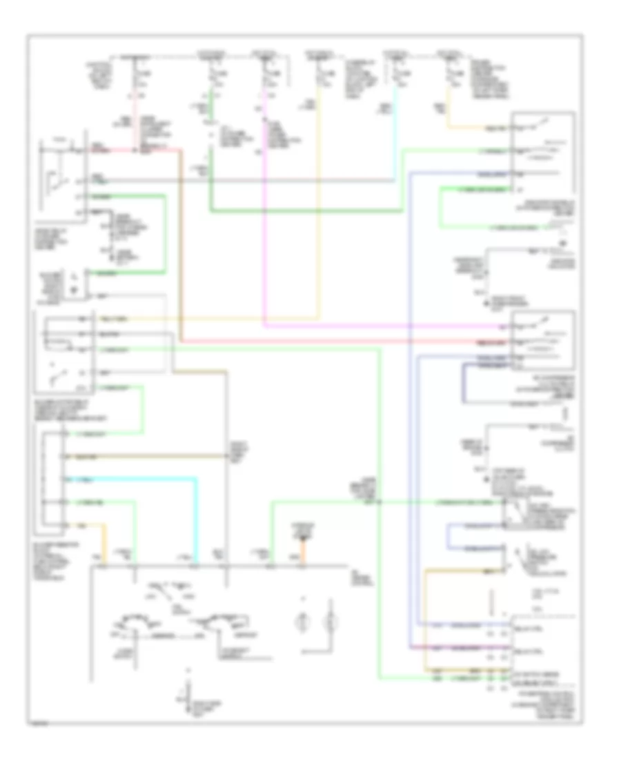
Heater Wiring Diagram for Dodge Dakota 2000

List of elements for Heater Wiring Diagram for Dodge Dakota 2000:
- (near battery) g111
- (next to breakout for chassis harness) s113
- (right side of dash) g201
- 87a
- Blower motor (right side of hvac housing)
- Blower motor relay (inside of glove box opening, next to energy absorbing bracket)
- Blower motor relay control
- Blower resistor block (in firewall plenum panel, below right side of windshield)
- C90
- Defrost
- Fan switch
- Fuse 10a
- Fuse 40a
- Fuse d 10a
- Fuse/relay block (mounted on junction block, left end of dash)
- Heat
- Heater control
- Hevac relay (in power distribution center)
- High
- High/low
- Hot at all times
- Hot in run
- Hot in run or start
- Illum
- Interior lights system
- Junction block (on left end of dash)
- Low
- Med 1
- Med 2
- Mode switch
- Off
- Power distribution center (in engine compartment, on left inner fender panel)
- Powertrain control module (in engine compartment, on right inner fender panel)
- S221 (right side of dash)
- S258 (near instrument cluster connector c2 breakout)
- Tan
Manual A/C Wiring Diagram for Dodge Dakota 2000
List of elements for Manual A/C Wiring Diagram for Dodge Dakota 2000:
- (near battery) g111
- (near breakout for chassis harness) s113
- (near breakout for cigar lighter) s217
- (near instrument cluster connector c2 breakout) s258
- (near right headlamp breakout) s109
- (rear of engine) s108
- (right front inner fender) g101
- (right side of dash) g201
- (right side of dash) s221
- (top rear of valve cover) g114 (2.5l) g119 (3.9l, 4.7l & 5.9l) (right front of engine)
- 2.5l
- 3.9l, 4.7l & 5.9l
- 87a
- A/c compressor clutch
- A/c compressor clutch relay (in power distribution center)
- A/c heater control
- A/c high pressure switch (on discharge line, near a/c compressor)
- A/c low pressure switch (on accumulator)
- A/c select input
- A/c select switch
- A/c switch sense
- Blower motor (right side of hvac housing)
- Blower motor relay (inside of glove box opening, next to energy absorbing bracket)
- Blower resistor block (in firewall plenum panel, below right side of windshield)
- C13
- C20
- C27
- C90
- Defrost
- Fan switch
- Fuse 10a
- Fuse 20a
- Fuse 30a
- Fuse 40a
- Fuse d 10a
- Fuse/relay block (mounted on junction block, left end of dash)
- Heat
- Hevac relay (in power distribution center)
- Hi/lo a/c
- High
- Hot at all times
- Hot in run
- Hot in run or start
- Interior lights system
- J/c 1 (in power distribution center)
- Junction block (on left end of dash)
- Low
- Max
- Med 1
- Med 2
- Mode switch
- Off
- Power distribution center (in engine compartment, on left inner fender panel)
- Powertrain control module (pcm) (in engine compartment, on right inner fender panel)
- Radiator fan motor
- Radiator fan relay (in power distribution center)
- Red/ tan
- Red/tan
- Relay ctrl
- S159 (near power distribution center)
- Tan
 English