AIR CONDITIONING
Automatic A/C Wiring Diagram (1 of 3) for Ford Cab & Chassis F350 Super Duty 2008

List of elements for Automatic A/C Wiring Diagram (1 of 3) for Ford Cab & Chassis F350 Super Duty 2008:
- (at top left of hvac module) electric heater
- (crew cab & regular cab: in left "a" pillar) (super cab: behind left side of dash)
- (in extension assembly-a/c blower motor feed harness, near top of hvac housing) s250
- (in extension assembly-a/c blower motor feed harness, near top of hvac housing) s251
- 150a
- Ambient
- Battery
- Battery junction box (bjb) (at left rear of engine compt)
- Blower command
- Blower motor relay
- C2280a
- C2280b
- C2280e
- C228a
- C2357b
- C2463a
- C2463b
- C2463c
- Cable pro
- Cbp37
- Ch122
- Ch123
- Ch207
- Ch208
- Ch211
- Ch213
- Ch228
- Ch229
- Ch237
- Ch239
- Chs29
- Chs30
- Computer data lines system
- Driver temperature blend door actuator (at bottom of hvac assembly)
- Drv htd seat sw
- Drv sun load
- Drv temp a+
- Drv temp b+
- Drv temp feedback
- Front blower rly
- Fuse 10a
- Fuse 40a
- Fuse 5a
- G300
- Gd133
- Gnd
- Heated mirror relay
- Hot at all times
- Hot in run or acc
- Hot in run or start
- Hscan+
- Hscan-
- Hvac-eatc
- Incar temp sn
- Lh111
- Mode actr a+
- Mode actr b+
- Mode actr feedback
- Mscan+
- Mscan-
- Nca
- Panel/defrost mode actuator (at left side of hvac assembly)
- Pass htd seat sw
- Pass sun load
- Pass temp a+
- Pass temp b+
- Pass temp feedback
- Passenger temperature blend door actuator (at top middle of hvac assembly)
- Rear def htd mirror
- Recirc door a+
- Recirc door b+
- Recirculation door actuator (at right side of hvac case)
- Red
- Rh111
- S104
- S143
- S144
- S145
- S206
- S224
- Sbp15
- Smart junction box (on passenger side kick panel)
- Steering wheel sw in
- Vbat
- Vdb06
- Vdb07
- Vh101
- Vh407
- Vh414
- Vh416
- Vh417
- Vh436
- Vh440
- Vh441
- Vh444
- Vign
- Vref actr
- Vref rtn
- W/ electric heater
- W/o electric heater
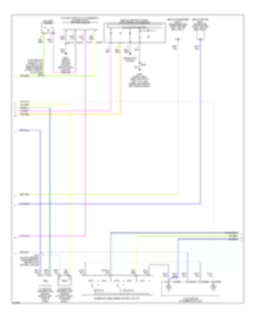
Automatic A/C Wiring Diagram (2 of 3) for Ford Cab & Chassis F350 Super Duty 2008
List of elements for Automatic A/C Wiring Diagram (2 of 3) for Ford Cab & Chassis F350 Super Duty 2008:
- (at right side of hvac assembly) blower motor control module
- (behind center of dash) autolamp/sunload sensor
- (below driver seat) driver side front heated seat relay
- (below passenger seat) passenger side front heated seat relay
- (in extension
- Assembly-a/c blower motor feed harness, at right side of hvac case)
- Blower motor
- C218a
- C218b
- Ch218
- Ch402
- Clock spring (in steering column)
- Fan down
- Fan up
- G203 (behind center of dash, behind audio control module)
- G300 (crew cab & regular cab: in left "a" pillar) (super cab: behind left side of dash)
- Gd115
- Headlights system
- In vehicle temperature sensor (behind left side of dash)
- Outside air temperature sensor (at right front of engine compt)
- S210 (in main harness, near breakout behind audio control module)
- S225
- S257
- Solid state control
- Steering wheel/speed control switch
- Vh101
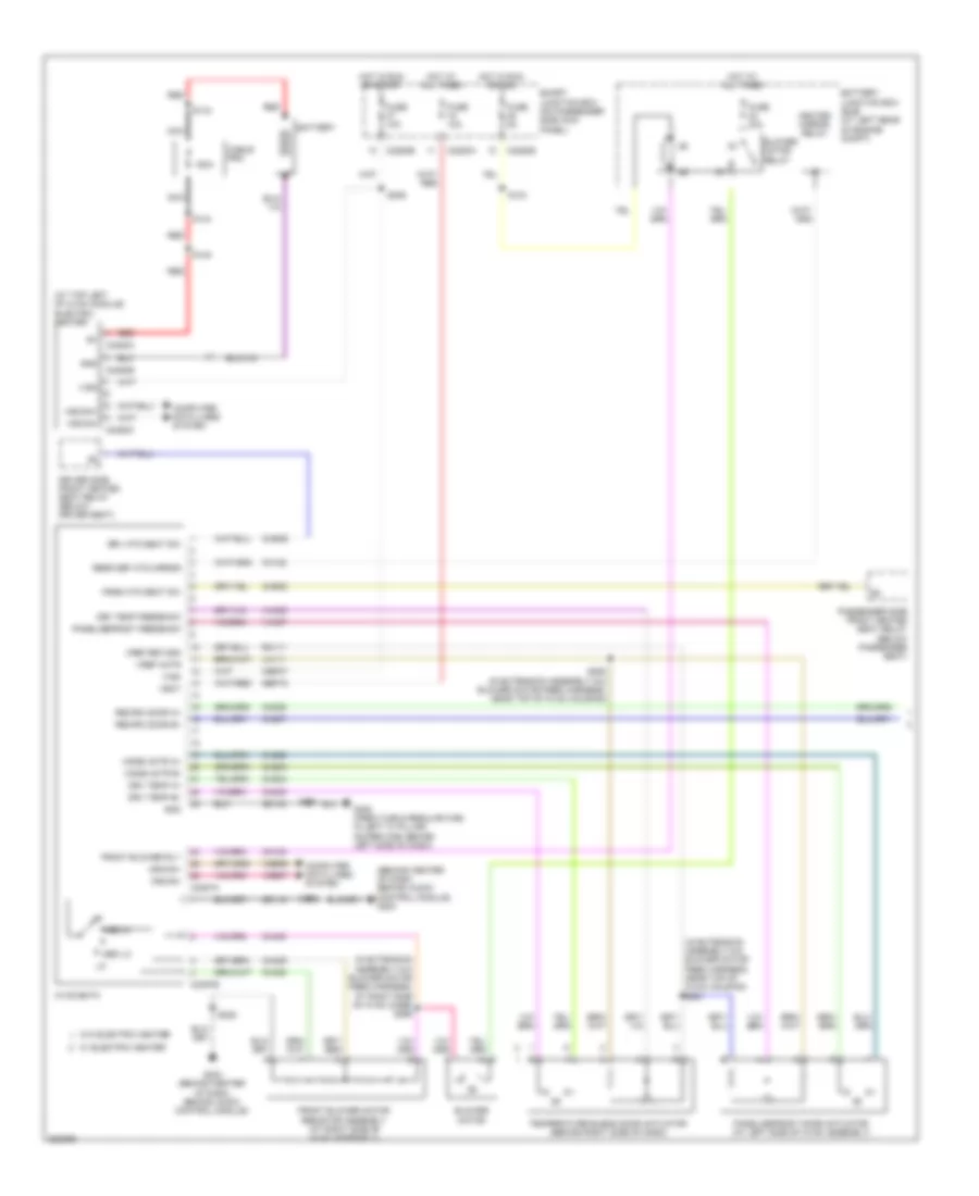
Automatic A/C Wiring Diagram (3 of 3) for Ford Cab & Chassis F350 Super Duty 2008
List of elements for Automatic A/C Wiring Diagram (3 of 3) for Ford Cab & Chassis F350 Super Duty 2008:
- (at front of engine) (diesel) engine coolant temperature (ect) sensor
- (diesel)
- (diesel) (gas)
- (gas)
- (in engine control sensor & fuel charge harness, near breakout to front right side of engine, on top) s133
- (in engine control sensor harness, near breakout to front center of engine compt)
- (in engine control sensor harness, near breakout to front right side of engine, on top) s1013
- A/c clutch diode
- A/c clutch relay
- A/c clutch solenoid
- A/c cycling switch
- A/c cycling switch (gas)
- A/c high pressure switch (at right side of engine compt)
- Accr
- Accs
- Acpsw
- Audio/climate control switch
- Battery junction box (bjb) (at left rear of engine compt)
- Brake pressure switch (at bottom of master cylinder)
- C1232b
- C1232e
- C175b
- C175e
- Ce237
- Cec11
- Ch302
- Ch421
- Ch425
- Cht
- Control
- Cylinder head temperature sensor (6.8l: on right cylinder head) (5.4l: at rear of block, under intake)
- Diesel
- Dual pressure switch (diesel) (at right front of engine)
- Ect
- Electric fan clutch (at front of engine)
- Engine controls system
- Fuse 10a
- Fuse 20a
- Fuse 50 (gas) 30a fuse 39 (diesel) 50a
- G103 (at right rear of engine compt)
- G108 (at left rear of engine compt)
- Gas
- Gd119
- Gnd
- Hot at all times
- Interior lights system
- Kapwr
- Media
- Mpr (pcm-rc)
- Nca control
- Nca gnd
- Nca sig
- Nca vbpwr
- Nca vpwr
- Near breakout to left front of frame)
- Pcm power relay
- Powertrain control module (pcm) (at left side of firewall)
- Re405
- S1008 (in engine control sensor harness, near breakout to right rear of engine compt)
- S1009 (in engine control sensor harness, near breakout to front right side of engine, on top)
- S1010 (in engine control sensor harness, near breakout to front right side of engine, on top)
- S114
- S115
- S117 (diesel)
- S120
- S128
- S154 (gas)
- S158 (gas)
- Sbb36
- Seek +
- Seek -
- Sig
- Sig rtn
- Sound systems
- Temp +
- Temp -
- Vbpwr
- Ve712
- Ve716
- Vec03
- Vec10
- Vol +
- Vol -
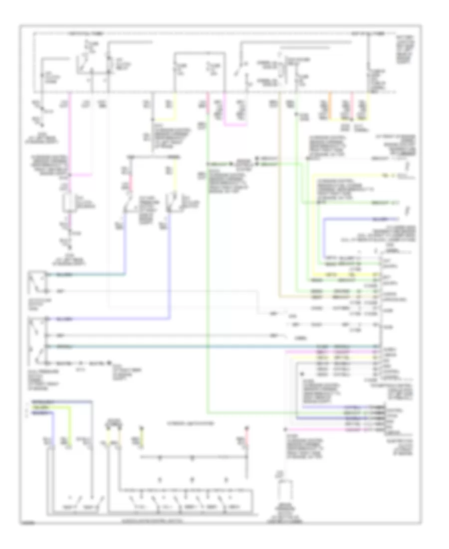
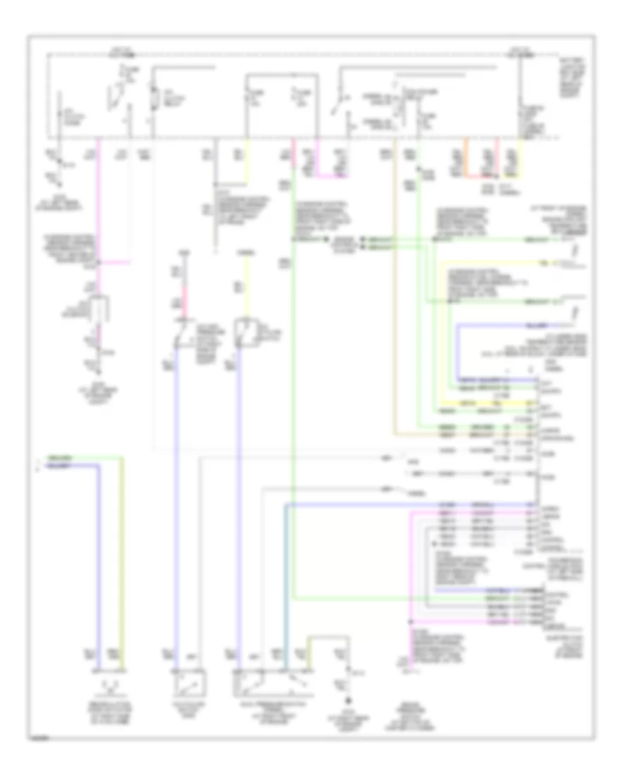
Manual A/C Wiring Diagram (1 of 2) for Ford Cab & Chassis F350 Super Duty 2008
List of elements for Manual A/C Wiring Diagram (1 of 2) for Ford Cab & Chassis F350 Super Duty 2008:
- (at top left of hvac module) electric heater
- (behind center of dash, behind audio control module) g203
- (in extension assembly-a/c blower motor feed harness, at right side of hvac case) s256
- (in extension assembly-a/c blower motor feed harness, near top of hvac housing) s251
- 150a
- Battery
- Battery junction box (bjb) (at left rear of engine compt)
- Blower motor
- Blower motor relay
- C2280a
- C2280b
- C2280e
- C2357a
- C2357b
- C2463a
- C2463b
- C2463c
- Cable pro
- Cbp37
- Ch122
- Ch123
- Ch202
- Ch203
- Ch207
- Ch208
- Ch233
- Ch234
- Ch428
- Ch429
- Ch430
- Chs29
- Chs30
- Computer data lines system
- Driver side front heated seat relay (below driver seat)
- Drv htd seat sw
- Drv temp a+
- Drv temp b+
- Drv temp feedback
- Front blower motor resistor assembly (at right side of hvac assembly)
- Front blower rly
- Fuse 10a
- Fuse 40a
- Fuse 5a
- G203 (behind center of dash, behind audio control module)
- G300 (crew cab & regular cab: in left "a" pillar) (super cab: behind left side of dash)
- Gd115
- Gd133
- Gnd
- Heated mirror relay
- Hot at all times
- Hot in run or acc
- Hot in run or start
- Hscan+
- Hscan-
- Hvac-emtc
- Lh111
- Med hi
- Med lo
- Mode actr a+
- Mode actr b-
- Mscan+
- Mscan-
- Nca
- Panel/defrost feedback
- Panel/defrost mode actuator (at left side of hvac assembly)
- Pass htd seat sw
- Passenger side front heated seat relay (below passenger seat)
- Rear def htd mirror
- Recirc door a+
- Recirc door b+
- Red
- Rh111
- S104
- S143
- S144
- S145
- S206
- S224
- S225
- S250 (in extension assembly-a/c blower motor feed harness, near top of hvac housing)
- Sbp15
- Smart junction box (on passenger side kick panel)
- Temperature blend door actuator (behind right side of dash)
- Vbat
- Vdb06
- Vdb07
- Vh437
- Vh439
- Vign
- Vref actr
- Vref return
- W/ electric heater
- W/o electric heater
Manual A/C Wiring Diagram (2 of 2) for Ford Cab & Chassis F350 Super Duty 2008
List of elements for Manual A/C Wiring Diagram (2 of 2) for Ford Cab & Chassis F350 Super Duty 2008:
- (at front of engine) (diesel) engine coolant temperature (ect) sensor
- (diesel)
- (diesel) (gas)
- (gas)
- (in engine control sensor & fuel charge harness, near breakout to front right side of engine, on top) s133
- (in engine control sensor harness, near breakout to front center of engine compt)
- (in engine control sensor harness, near breakout to front right side of engine, on top) s1013
- A/c clutch diode
- A/c clutch relay
- A/c clutch solenoid
- A/c cycling switch
- A/c cycling switch (gas)
- A/c high pressure switch (at right side of engine compt)
- Accr
- Accs
- Acpsw
- Battery junction box (bjb) (at left rear of engine compt)
- Brake pressure switch (at bottom of master cylinder)
- C1232b
- C1232e
- C175b
- C175e
- Ce237
- Cec11
- Ch302
- Ch421
- Ch425
- Cht
- Control
- Cylinder head temperature sensor (6.8l: on right cylinder head) (5.4l: at rear of block, under intake)
- Diesel
- Dual pressure switch (diesel) (at right front of engine)
- Ect
- Electric fan clutch (at front of engine)
- Engine controls system
- Fuse 10a
- Fuse 20a
- Fuse 50 (gas) 30a fuse 39 (diesel) 50a
- G103 (at right rear of engine compt)
- G108 (at left rear of engine compt)
- Gas
- Gd119
- Gnd
- Hot at all times
- Kapwr
- Mpr (pcm-rc)
- Nca control
- Nca gnd
- Nca sig
- Nca vbpwr
- Nca vpwr
- Near breakout to left front of frame)
- Pcm power relay
- Powertrain control module (pcm) (at left side of firewall)
- Re405
- Recirculation door actuator (at right side of hvac case)
- S1008 (in engine control sensor harness, near breakout to right rear of engine compt)
- S114
- S115
- S120
- S128
- S154 s117 (diesel)
- S158 (gas)
- Sbb36
- Sig
- Sig rtn
- Vbpwr
- Ve712
- Ve716
- Vec03
- Vec10