AIR CONDITIONING
Manual A/C Wiring Diagram, with Stripped Chassis for Ford E450 Super Duty 2010

List of elements for Manual A/C Wiring Diagram, with Stripped Chassis for Ford E450 Super Duty 2010:
- (4.6l: engine control sensor wiring harness & fuel charge, near breakout to evap canister purge valve) (6.8l: engine control sensor wiring harness & fuel charge, in breakout to powertrain control module (pcm)) s172
- (engine control sensor wiring harness, near breakout to anti-lock brake system module)
- (not used)
- 4.6l & 5.4l
- 6.8l
- A/c clutch relay
- A/c compressor clutch field coil (lower right front of engine)
- Accr
- Accs
- Battery junction box (bjb) (left front of engine compt)
- Blower motor relay
- C1551e
- C175b
- C175e
- C2280b
- Ch302
- Ch421
- Cht
- Customer access connector (right front of engine compt)
- Cylinder head temperature sensor (front of left cylinder head)
- Engine controls system
- Except 5.4l
- Fuse 10a
- Fuse 50a
- G100 (right side of engine compt)
- G101 (left front corner of engine compt)
- Hot at all times
- Hot in start or run
- Hot w/ pcm power relay energized
- Powertrain control module (pcm) (center rear of engine compt)
- Re405
- S108 (engine control sensor wiring harness, near breakout to a/c cycling switch)
- S123 (engine control sensor wiring harness, near breakout to c144)
- S124
- Sigrtn
- Smart junction box (sjb) (left side of dash)
- Ve712
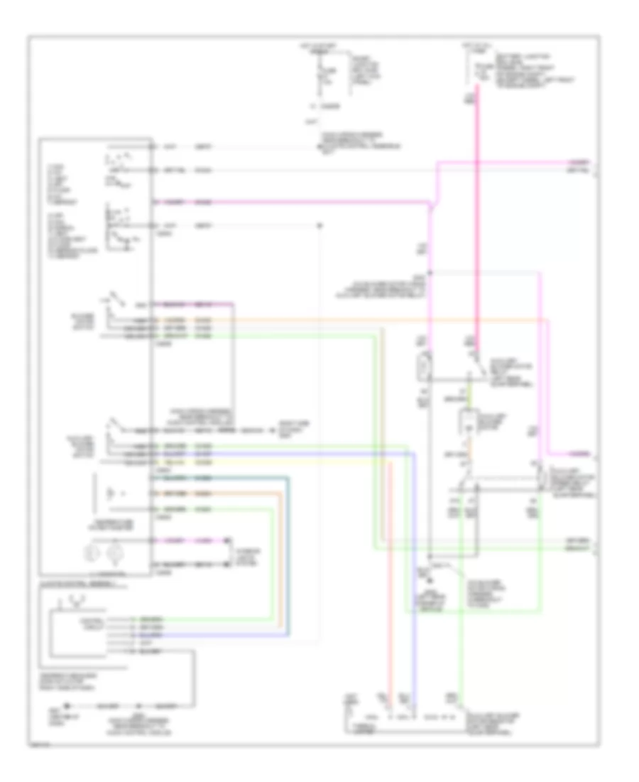
Manual A/C Wiring Diagram, without Stripped Chassis (1 of 2) for Ford E450 Super Duty 2010
List of elements for Manual A/C Wiring Diagram, without Stripped Chassis (1 of 2) for Ford E450 Super Duty 2010:
- (a/c blower motor wiring harness, in breakout to c405)
- (center of dash)
- (main wiring harness, near breakout to audio control module)
- (main wiring harness, near breakout to climate control assemble) s217
- (not used)
- (right side of dash) g200
- 0) off 5) max 6) normal 7) vent 8) floor/vent 9) floor 10) defrost/floor 11) defrost
- 1) max 2) a/c 3) vent 4) off 5) floor 6) mix 7) defrost
- 87a
- Auxiliary blower motor
- Auxiliary blower motor relay (left rear quarterpanel)
- Auxiliary blower motor resistor (left rear quarterpanel)
- Auxiliary blower motor speed relay (left rear quarterpanel)
- Auxiliary blower motor switch
- Battery junction box (bjb) (diesel: right front of engine compt) (except diesel: left front of engine compt)
- Blower motor switch
- C2280b
- C294a
- C294b
- C294c
- C294d
- C294e
- Cbp37
- Ch202
- Ch203
- Ch204
- Ch428
- Ch429
- Ch430
- Ch434
- Ch435
- Cha06
- Cha07
- Cha08
- Circuit
- Climate control assembly
- Control
- Fuse 10a
- Fuse 50a
- G201
- G403 (left rear corner of vehicle)
- Gd115
- Gd116
- Gnd
- High
- Hot at all times
- Hot in start or run
- Illumination
- Interior lights system
- Mid high
- Mid low
- S264 (main wiring harness, near breakout to audio control module)
- S265
- S400 (a/c blower motor wiring harness, near breakout to auxiliary blower motor relay)
- S401
- Smart junction box (sjb) (left kick panel)
- Temperature blend door actuator (right side of dash)
- Temperature potentiometer
- Thermal limiter
- Vlno4
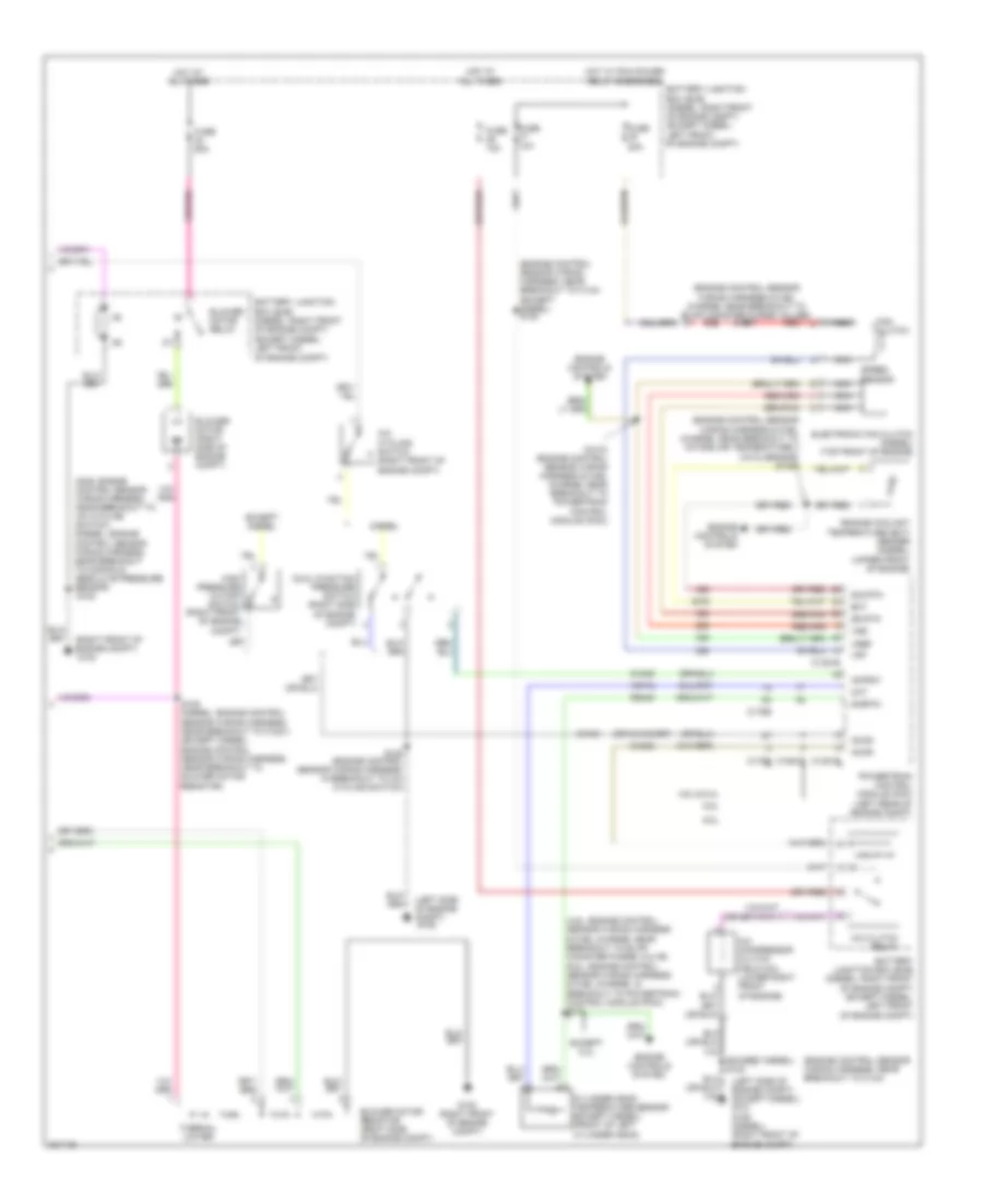
Manual A/C Wiring Diagram, without Stripped Chassis (2 of 2) for Ford E450 Super Duty 2010
List of elements for Manual A/C Wiring Diagram, without Stripped Chassis (2 of 2) for Ford E450 Super Duty 2010:
- (4.6l: engine control sensor wiring harness & fuel charge, near breakout to evap canister purge valve) (6.8l: engine control sensor wiring harness & fuel charge, in breakout to powertrain control module (pcm)) s172
- (engine control sensor wiring harness, near breakout to c134) (except diesel) s124
- (engine control sensor wiring harness & fuel charge, near breakout to evap canister purge valve6) s1057
- (engine control sensor wiring harness & fuel charge, near breakout to intake air temperature 2 (iat2) sensor) s1059
- (engine control sensor wiring harness, near breakout to c144)
- (except diesel) s123
- (gas: engine control sensor wiring harness, near breakout to a/c cycling switch) (diesel: engine control sensor wiring harness, near breakout to manifold absolute pressure sensor)
- (left side of engine compt)
- (left side of engine compt) (except diesel) g101 g106 (diesel) (right front of engine compt)
- (or ch419)
- (right front of engine compt)
- 4.6l & 5.4l
- 6.0l
- 6.8l
- A/c clutch relay
- A/c compressor clutch field coil (lower right front of engine)
- A/c cycling switch (right front of engine compt)
- Accr
- Accs
- Acpsw
- Battery junction box (bjb) (diesel: right front of engine compt) (except diesel: left front
- Battery junction box (bjb) (diesel: right front of engine compt) (except diesel: left front of engine compt)
- Blower motor (right side of engine compt)
- Blower motor relay
- Blower motor resistor (right side of engine compt)
- C1381b
- C1381e
- C1551e
- C175b
- C175e
- Ch302
- Ch421
- Ch425
- Cht
- Cylinder head temperature sensor (except diesel) (front of left cylinder head)
- Diesel
- Dual function pressure switch (right side of engine compt)
- Ect
- Electronic fan clutch (diesel) (top front of engine)
- Engine controls system
- Engine coolant temperature (ect) sender (diesel) (upper front of engine)
- Except 5.4l
- Except diesel
- Fan clutch
- Fuse 10a
- Fuse 20a
- Fuse 50a
- G100
- G100 (right front of engine compt)
- G105
- High pressure cutoff switch (right front of engine compt)
- Hot at all times
- Hot w/ pcm power relay energized
- Nca
- Of engine compt)
- Powertrain control module (pcm) (left rear of engine compt)
- Re405
- Red
- S1010 (engine control sensor wiring harness & fuel charge, near breakout to powertrain control module (pcm))
- S105 (diesel: engine control sensor wiring harness, near breakout to c1221) (except diesel: engine control sensor wiring harness, near breakout to blower motor resistor)
- S108
- S125 (engine control sensor wiring harness, in breakout to a/c cycling switch)
- Sig rtn
- Sigrtn
- Speed sensor
- Ss rtn
- Thermal limiter
- Vdf
- Ve712
- Vref
- Vss