AIR CONDITIONING
Manual A/C Wiring Diagram, with Stripped Chassis for Ford Econoline E150 2007

List of elements for Manual A/C Wiring Diagram, with Stripped Chassis for Ford Econoline E150 2007:
- (customer access)
- A/c demand signal
- A/c on input signal
- Battery junction box (bjb) (left side of engine compt)
- Blower motor relay
- C1026
- C175e
- Central junction box (cjb) (behind left side of dash)
- Fuse 15a
- Fuse 50a
- G114 (left rear of engine compt)
- Hot at all times
- Hot in run
- Powertrain control module (pcm) (left rear of engine compt)
- S195
- To body builder connector
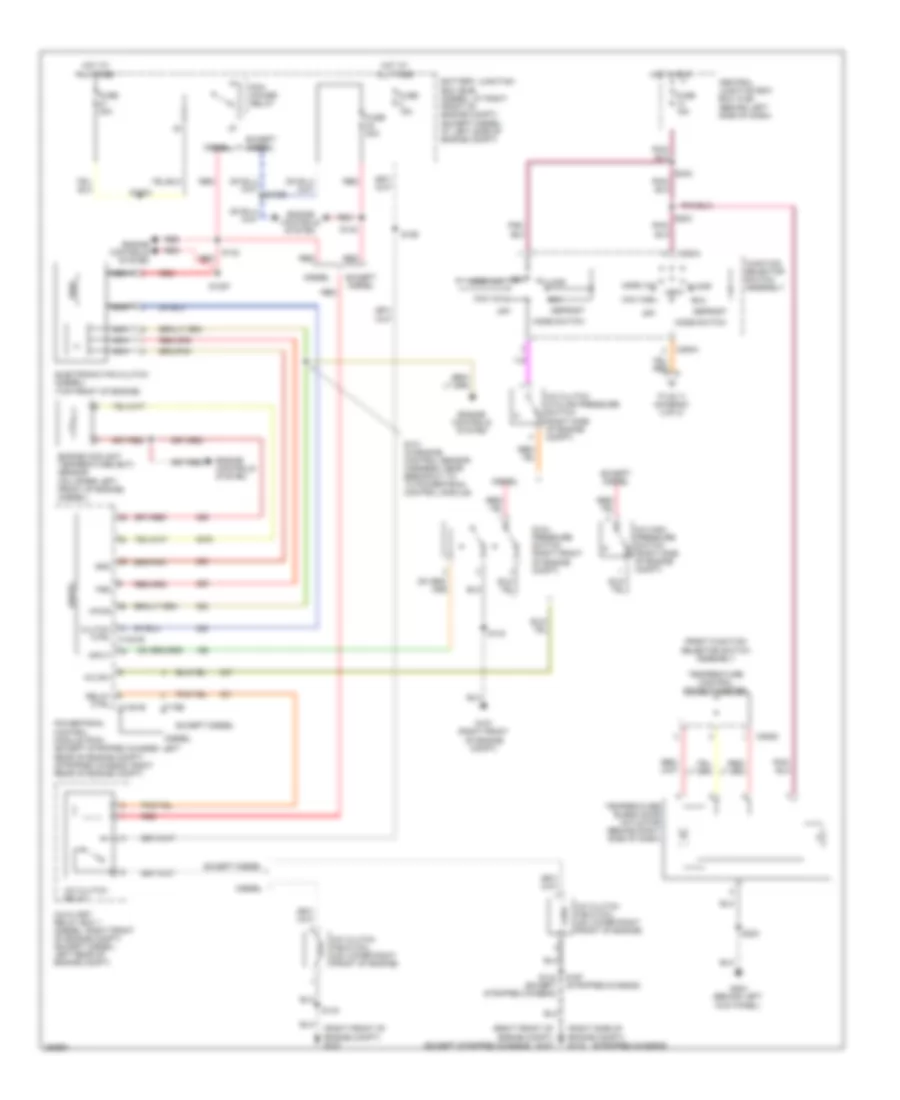
Manual A/C Wiring Diagram, without Stripped Chassis (1 of 2) for Ford Econoline E150 2007
List of elements for Manual A/C Wiring Diagram, without Stripped Chassis (1 of 2) for Ford Econoline E150 2007:
- (except stripped chassis)
- (right front of engine compt) g107
- (right side of engine compt) g115
- (stripped chassis)
- A/c clutch cycling pressure switch (right side of engine compt)
- A/c clutch field coil (on lower right front of engine)
- A/c clutch relay
- A/c high pressure switch (right side of engine compt)
- A/c sw
- Auxiliary relay box 1 (diesel: right front of engine compt) (except diesel: left rear of engine compt)
- Battery junction box (bjb) (diesel: at right front of engine compt) (except diesel: at left side of engine compt)
- C1381b
- C175e
- C294a
- C294d
- Central junction box box (cjb) (behind left side of dash)
- Clutch ctrl c1381e
- Defrost
- Diesel
- Dual pressure switch (right front of engine compt)
- Electronic fan clutch (diesel) (top front of engine)
- Engine controls system
- Engine coolant temperature (ect) sensor (on upper left front of engine) (diesel)
- Except diesel
- Floor
- Front function selector switch assembly
- Fss
- Function selector switch assembly
- Fuse 15a
- Fuse 20a
- Fuse 30a
- G107 (right front of engine compt)
- G204 (behind left kick panel)
- Gnd
- Hot at all times
- Hot in run
- Input
- Max a/c
- Mix
- Mode switch
- Nca
- Norm a/c
- Off
- Pcm power relay
- Powertrain control module (pcm) (except stripped chassis: left rear of engine compt) (stripped chassis: right rear of engine compt)
- Red
- Relay ctrl
- S101 (in engine control sensor harness, near breakout to to powertrain control module)
- S1033
- S1057
- S142
- S143
- S143 (except stripped chassis)
- S186
- S197 (stripped chassis)
- S203
- S223
- S242
- Temperature blend door actuator (behind right side of dash)
- Temperature control potentiometer
- To s111 (diagram 2 of 2)
- Vent
- Vent norm a/c
- Vpwr
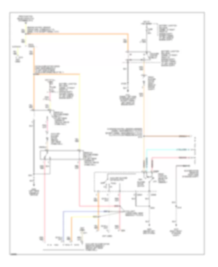
Manual A/C Wiring Diagram, without Stripped Chassis (2 of 2) for Ford Econoline E150 2007
List of elements for Manual A/C Wiring Diagram, without Stripped Chassis (2 of 2) for Ford Econoline E150 2007:
- (a/c blower motor wiring harn, near breakout to left side of rear a/c blower speed relay no. 1) s400
- (in engine control sensor harness) (diesel: near breakout to c144) (except diesel: near breakout to a/c clutch cycling pressure switch) s144
- (not used)
- (taillight wiring harn, near breakout to c315)
- Auxiliary blower motor (behind left rear wheelwell)
- Auxiliary blower motor resistor assembly (behind left rear wheelwell)
- Auxiliary blower motor switch
- Battery junction box (bjb) (diesel: at right front of engine compt) (except diesel: at left side of engine compt)
- Blower motor relay
- Blower motor resistor (right side of engine compt)
- Blower motor switch
- C294b
- C294c
- C311
- C312
- C925
- Cutaway
- Diesel: c140, except diesel: c101) s111
- From function selector switch (diagram 1 of 2)
- Front blower motor (right rear of engine compt)
- Front function selector switch assembly
- Fuse 50a
- G101 (diesel: left side of engine compt) (except diesel: left front of engine compt)
- G107 (right front of engine compt)
- G203 (behind left end of dash)
- G400 (left rear corner of vehicle)
- High
- Hot at all times
- Low
- Off
- Rear a/c blower speed relay 1 (in left rear corner of vehicle, above wheelwell)
- Rear a/c blower speed relay 2 (in left rear corner of vehicle, above wheelwell)
- S1029
- S143
- S202
- S303
- S304
- S305
- S401
- Van & wagon