AIR CONDITIONING
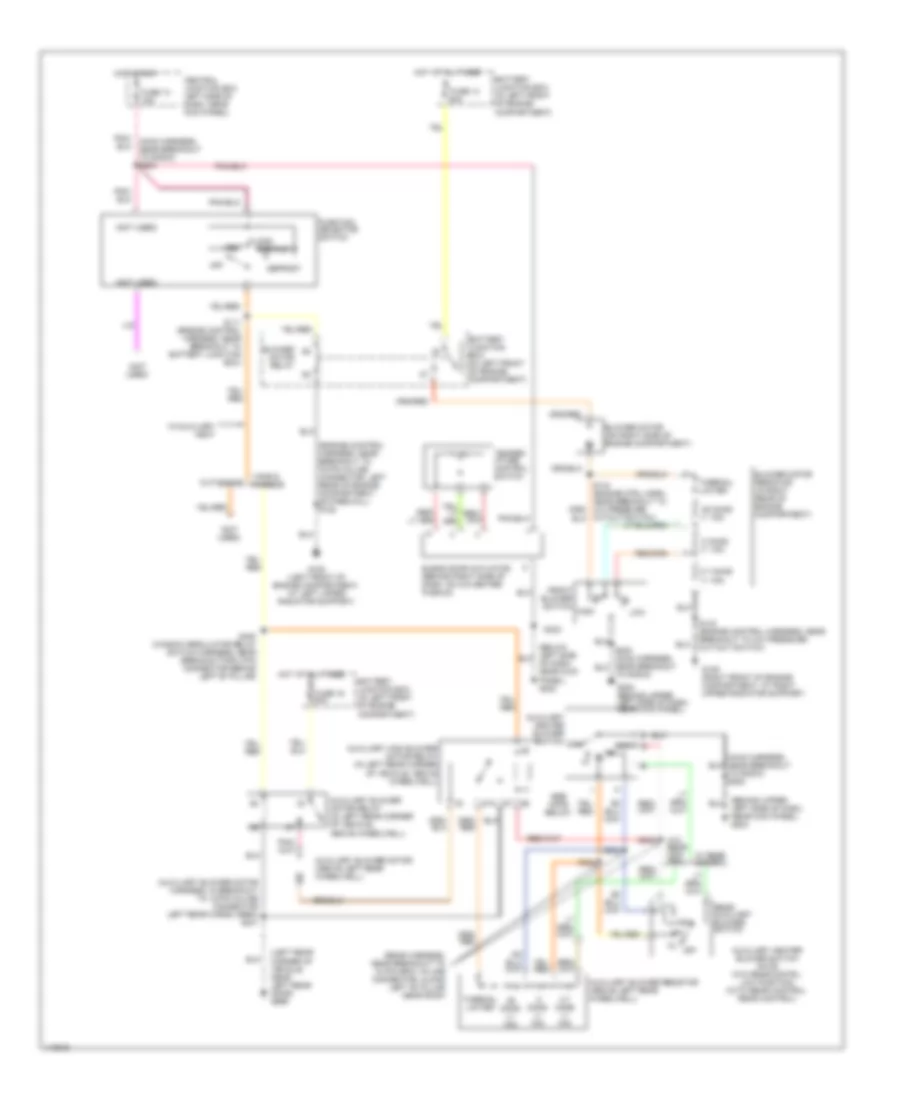
Heater Wiring Diagram, with Stripped Chassis for Ford Econoline E250 2001

List of elements for Heater Wiring Diagram, with Stripped Chassis for Ford Econoline E250 2001:
- (engine control harness, near breakout to 42 pin in-line connector, left rear of engine compartment below access cover) s195
- (left rear of engine compartment, near master cylinder) g116
- Battery junction box (in left front of engine compartment)
- Blower motor
- Blower motor relay
- Fuse 50a
- Fused blower motor feed
- Hot at all times
Heater Wiring Diagram, without Stripped Chassis for Ford Econoline E250 2001
List of elements for Heater Wiring Diagram, without Stripped Chassis for Ford Econoline E250 2001:
- (auxiliary blower motor harness, in breakout to 12-pin in-line connector left rear cargo area) s401
- (behind upper left side of dash, near kick panel) g202
- (below left side of dash, near kick panel) g202
- (engine control harness, near breakout to 76 pin in-line connector, left rear of engine compartment, on firewall) s122
- (left rear corner of vehicle, near left rear door) g999
- (main harness near breakout to radio) s202
- (not used)
- (rear harness, near breakout to 12 pin gray in-line connector, along left "b" pillar near roof)
- .25 ohms +/- 10%
- .8 ohms +/- 10%
- 2.7 ohms +/- 10%
- 87a
- Auxiliary blower motor (above left rear wheelwell)
- Auxiliary blower motor relay (in left rear corner of vehicle, above wheelwell)
- Auxiliary blower resistor (above left rear wheelwell)
- Auxiliary heater blower switch note: (w/o rear contrl: low position) (with rear control: rear control)
- Auxiliary heater blower switch off
- Auxiliary high blower motor relay (in left rear corner of vehicle, above wheelwell)
- Battery junction box (in left front of engine compartment)
- Blend door actuator (behind right side of dash, on a/c-heater plenum)
- Blower motor (on right side of engine compartment)
- Blower motor relay
- Blower motor resistor (in right rear of engine compartment)
- Central junction box left side of dash, near kick panel)
- Cutaways
- Cutout switch)
- Def/flr
- Defrost
- Floor
- Front blower switch
- Function selector switch
- Fuse 13 15a
- Fuse 13 50a
- Fuse 16 50a
- G108 (left front of engine compartment, at left upper radiator support)
- G109 (right front of engine compartment, at right upper radiator support)
- G202 (behind upper left side of dash, near kick panel)
- High
- Hot at all times
- Hot in run
- Low
- Off
- Pnk/ (main harness, near breakout to radio) s203
- Rear auxiliary blower switch
- S111 (engine control harness, near breakout to battery junction box)
- S143 (engine control harness, near breakout to a/c pressure cut-out switch)
- S202 (main harness, near breakout to radio)
- S303
- S304
- S305
- S323
- S400 (window regulator relay switch harness, near breakout for 2 pin connector behind left "b" pillar)
- See note below
- Temper- ature control switch
- Thermal limiter
- Vans & wagons
- Vent
- W/ rear control
- W/auxiliary heat
- W/o rear con- trol
4.2L
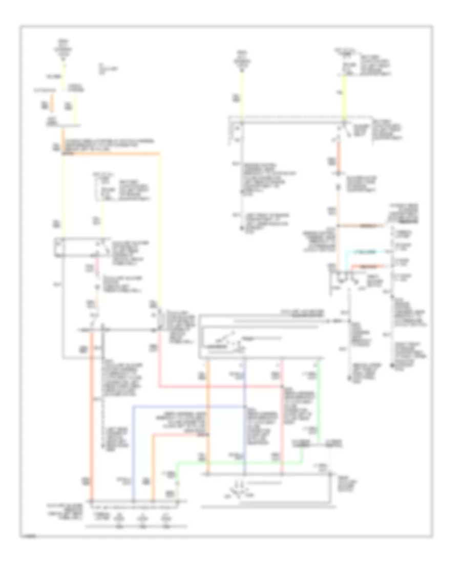
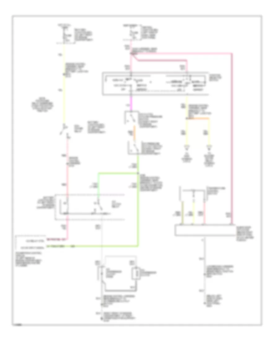
4.2L, Manual A/C Wiring Diagram, with Stripped Chassis for Ford Econoline E250 2001
List of elements for 4.2L, Manual A/C Wiring Diagram, with Stripped Chassis for Ford Econoline E250 2001:
- (engine control harness, near breakout to battery junction box) s110
- (fuel charge harness, near breakout to fuel injector 6) s107
- (left rear of engine compartment, near master cylinder) g116
- (not used)
- (right rear of engine compartment) g105
- 87a
- A/c clutch relay
- A/c compressor clutch
- A/c compressor clutch diode
- A/c demand
- A/c on input signal
- A/c relay control
- A/c switch
- Battery junction box (in left front of engine compartment)
- Blower motor
- Blower motor relay
- C1001f
- Central junction box (left side of dash, near kick panel)
- Fuse 10a
- Fuse 15a
- Fuse 30a
- Fuse 50a
- Fused blower motor feed
- Hot at all times
- Hot in run
- Note: pcm power relay energized w/ignition switch in run or start position
- Pcm power relay
- Powertrain control module (in left rear of engine compartment, near brake master cylinder)
- Red
- S142 (engine control harness, near breakout to 8 pin in-line connector, center of engine compartment, near mass air flow sensor)
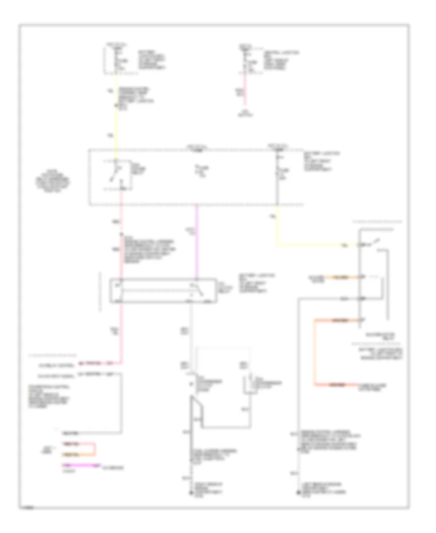
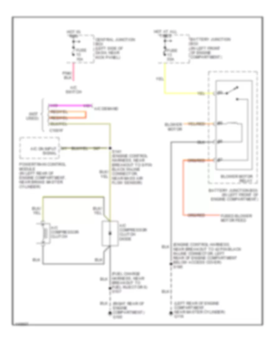
4.2L, Manual A/C Wiring Diagram, without Stripped Chassis for Ford Econoline E250 2001
List of elements for 4.2L, Manual A/C Wiring Diagram, without Stripped Chassis for Ford Econoline E250 2001:
- (below left side of dash, near left kick panel) g202
- (engine control harness) s142
- (engine control harness, near breakout to battery junction box) s110
- (fuel charge harness, near breakout to fuel injector 6) s107
- (lower dash harness, near breakout to brake pedal position (bpp) switch) s223
- (right front of engine compartment, at right upper radiator support) g109
- 87a
- A/c clutch cycling pressure switch (in right front of engine compartment)
- A/c clutch relay
- A/c compressor clutch
- A/c compressor clutch diode
- A/c on input signal
- A/c pressure cut-out switch (in right front of engine compartment)
- A/c relay control
- Battery junction box (in left front of engine compartment)
- Blend door actuator (behind right side of dash, on a/c heater plenum)
- Central junction box (left side of dash, near kick panel)
- Def/flr
- Defrost
- Floor
- Function selector switch
- Fuse 10a
- Fuse 15a
- Fuse 30a
- Hot at all times
- Hot in run
- Max a/c
- Norm a/c
- Note: pcm power relay energized w/ignition switch in run or start position
- Off
- Pcm power relay
- Powertrain control module (in left rear of engine compartment, near brake master cylinder)
- Red
- Temperature control switch
- To blower motor relay (diagram 2 of 2)
- To s400 (diagram 2 of 2)
- Vent
- Vent norm a/c
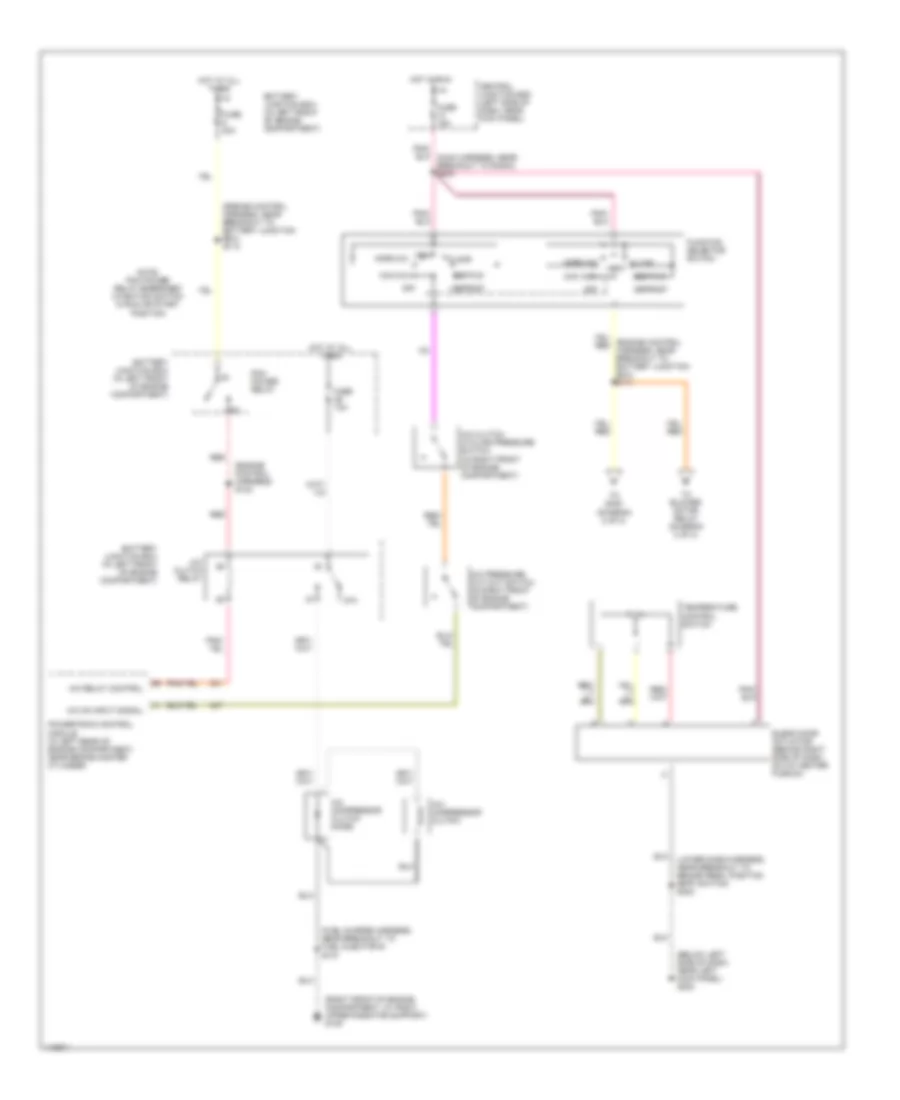
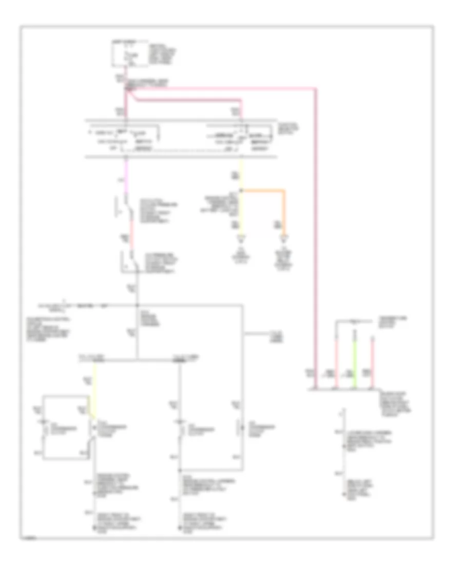
4.2L, Manual A/C Wiring Diagram, without Stripped Chassis for Ford Econoline E250 2001
List of elements for 4.2L, Manual A/C Wiring Diagram, without Stripped Chassis for Ford Econoline E250 2001:
- (behind upper left side of dash, near kick panel) g202
- (engine control harness, near breakout to 76 pin black in-line connector, left rear of engine compartment, on firewall) s122
- (in right rear of engine compartment) blower motor resistor
- (left front of engine compartment, at left upper radiator support) g108
- (left rear corner of vehicle, near left rear door) g999
- (not used)
- (rear harness, near breakout to 12 pin gray in-line connector, along left "b" pillar, near roof) s303
- (right front of engine compartment, at right upper radiator support) g109
- (window regulator relay switch harness, near breakout to 2 pin connector, behind left "b" pillar) s400
- .25 ohms +/- 10%
- .8 ohms +/- 10%
- 2.7 ohms +/- 10%
- 87a
- Auxiliary a/c-heater blower switch
- Auxiliary blower motor (above left rear wheelwell)
- Auxiliary blower motor relay (in left rear corner of vehicle, above wheelwell)
- Auxiliary blower resistor (above left rear wheelwell)
- Auxiliary high blower motor relay (in left rear corner of vehicle, above wheelwell)
- Battery junction box (in left front of engine compartment)
- Blower motor (on right side of engine compartment)
- Blower motor relay
- Cutaways
- From s111 (diagram 1 of 2)
- Front blower switch
- Fuse 50a
- High
- Hot at all times
- Low
- Low/rear
- Off
- Rear auxiliary blower switch
- S143 (engine control harness, near breakout to a/c pressure cutout switch)
- S144 (engine control harness, near breakout to a/c pressure cutout switch)
- S202 (main harness, near breakout to radio)
- S304 (rear harness, near breakout to 12 pin gray in-line connector, along left "b" pillar, near roof)
- S305 (rear harness, near breakout to 12 pin gray in-line connector, along left "b" pillar, near roof)
- S401 (auxiliary blower motor harness, in breakout to 12 pin gray in-line connector, left rear cargo area, near auxiliary blower motor)
- Thermal limiter
- Vans & wagons
- W/ auxiliary a/c
- W/ rear control
- W/o rear control
4.6L
4.6L, Manual A/C Wiring Diagram, without Stripped Chassis for Ford Econoline E250 2001
List of elements for 4.6L, Manual A/C Wiring Diagram, without Stripped Chassis for Ford Econoline E250 2001:
- (below left side of dash, near left kick panel) g202
- (engine control harness) s142
- (engine control harness, near breakout to a/c pressure cutout switch) s143
- (engine control harness, near breakout to battery junction box) s110
- (engine control harness, near breakout to battery junction box) s111
- (lower dash harness, near breakout to brake pedal position (bpp) switch) s223
- (right front of engine compartment, at right upper radiator support) g109
- 87a
- A/c clutch cycling pressure switch (in right front of engine compartment)
- A/c clutch relay
- A/c compressor clutch
- A/c compressor clutch diode
- A/c on input signal
- A/c pressure cut-out switch (in right front of engine compartment)
- A/c relay ctrl
- Battery junction box (in left front of engine compartment)
- Blend door actuator (behind right side of dash, on a/c heater plenum)
- Central junction box (left side of dash, near kick panel)
- Def/flr
- Defrost
- Floor
- Function selector switch
- Fuse 15a
- Fuse 30a
- Hot at all times
- Hot in run
- Max a/c
- Norm a/c
- Note: pcm power relay energized w/ignition switch in run or start position
- Off
- Pcm power relay
- Powertrain control module (in left rear of engine compartment, near brake master cylinder)
- Red
- S166 (engine control harness, near breakout to 8 pin in-line connector, center of engine compartment)
- Temperature control switch
- To blower motor relay (diagram 2 of 2)
- To s400 (diagram 2 of 2)
- Vent
- Vent norm a/c
4.6L, Manual A/C Wiring Diagram, without Stripped Chassis for Ford Econoline E250 2001
List of elements for 4.6L, Manual A/C Wiring Diagram, without Stripped Chassis for Ford Econoline E250 2001:
- (behind upper left side of dash, near kick panel) g202
- (engine control harness, near breakout to 76 pin black in-line connector, left rear of engine compartment, on firewall) s122
- (in right rear of engine compartment) blower motor resistor
- (left front of engine compartment, at left upper radiator support) g108
- (left rear corner of vehicle, near left rear door) g999
- (not used)
- (rear harness, near breakout to 12 pin gray in-line connector, along left "b" pillar, near roof) s303
- (right front of engine compartment, at right upper radiator support) g109
- (window regulator relay switch harness, near breakout to 2 pin connector, behind left "b" pillar) s400
- .25 ohms +/- 10%
- .8 ohms +/- 10%
- 2.7 ohms +/- 10%
- 87a
- Auxiliary a/c-heater blower switch
- Auxiliary blower motor (above left rear wheelwell)
- Auxiliary blower motor relay (in left rear corner of vehicle, above wheelwell)
- Auxiliary blower resistor (above left rear wheelwell)
- Auxiliary high blower motor relay (in left rear corner of vehicle, above wheelwell)
- Battery junction box (in left front of engine compartment)
- Blower motor (on right side of engine compartment)
- Blower motor relay
- Cutaways
- From s111 (diagram 1 of 2)
- Front blower switch
- Fuse 50a
- High
- Hot at all times
- Low
- Low/rear
- Off
- Rear auxiliary blower switch
- S143 (engine control harness, near breakout to a/c pressure cutout switch)
- S144 (engine control harness, near breakout to a/c pressure cutout switch)
- S202 (main harness, near breakout to radio)
- S304 (rear harness, near breakout to 12 pin gray in-line connector, along left "b" pillar, near roof)
- S305 (rear harness, near breakout to 12 pin gray in-line connector, along left "b" pillar, near roof)
- S401 (auxiliary blower motor harness, in breakout to 12 pin gray in-line connector, left rear cargo area, near auxiliary blower motor)
- Thermal limiter
- Vans & wagons
- W/ auxiliary a/c
- W/ rear control
- W/o rear control
5.4L
5.4L, Manual A/C Wiring Diagram, with Stripped Chassis for Ford Econoline E250 2001
List of elements for 5.4L, Manual A/C Wiring Diagram, with Stripped Chassis for Ford Econoline E250 2001:
- (left rear of engine compartment, near master cylinder) g116
- (not used)
- (right rear of engine compartment) g105
- A/c compressor clutch
- A/c compressor clutch diode
- A/c demand
- A/c on input signal
- A/c switch
- Battery junction box (in left front of engine compartment)
- Blower motor
- Blower motor relay
- Breakout to fuel injector 6) s107
- C1001f
- Central junction box (left side of dash, near kick panel)
- Fuse 15a
- Fuse 50a
- Fused blower motor feed
- Hot at all times
- Hot in run
- Powertrain control module (in left rear of engine compartment, near brake master cylinder)
5.4L, Manual A/C Wiring Diagram, without Stripped Chassis for Ford Econoline E250 2001
List of elements for 5.4L, Manual A/C Wiring Diagram, without Stripped Chassis for Ford Econoline E250 2001:
- (below left side of dash, near left kick panel) g202
- (engine control harness, near breakout to injection pressure sensor (ips)) s189
- (lower dash harness, near breakout to brake pedal position (bpp) switch) s223
- (right front of engine compartment, at right upper radiator support) g109
- 5.4l, 5.4l ngv & 6.8l
- 7.3l di turbo diesel
- A/c clutch cycling pressure switch (in right front of engine compartment)
- A/c compressor clutch
- A/c compressor clutch diode
- A/c on input signal
- A/c pressure cut-out switch (in right front of engine compartment)
- Blend door actuator (behind right side of dash, on a/c heater plenum)
- Central junction box (left side of dash, near kick panel)
- Def/flr
- Defrost
- Floor
- Function selector switch
- Fuse 15a
- Hot in run
- Max a/c
- Norm a/c
- Off
- Powertrain control module (in left rear of engine compartment, near brake master cylinder)
- S111 (engine control harness, near breakout to battery junction box)
- S141 (engine control harness)
- S143 (engine control harness, near breakout to a/c pressure cutout switch)
- Temperature control switch
- To blower motor relay (diagram 2 of 2)
- To s400 (diagram 2 of 2)
- Vent
- Vent norm a/c
5.4L, Manual A/C Wiring Diagram, without Stripped Chassis for Ford Econoline E250 2001
List of elements for 5.4L, Manual A/C Wiring Diagram, without Stripped Chassis for Ford Econoline E250 2001:
- (behind upper left side of dash, near kick panel) g202
- (engine control harness, near breakout to 76 pin black in-line connector, left rear of engine compartment, on firewall) s122
- (in right rear of engine compartment) blower motor resistor
- (left front of engine compartment, at left upper radiator support) g108
- (left rear corner of vehicle, near left rear door) g999
- (not used)
- (rear harness, near breakout to 12 pin gray in-line connector, along left "b" pillar, near roof) s303
- (right front of engine compartment, at right upper radiator support) g109
- (window regulator relay switch harness, near breakout to 2 pin connector, behind left "b" pillar) s400
- .25 ohms +/- 10%
- .8 ohms +/- 10%
- 2.7 ohms +/- 10%
- 87a
- Auxiliary a/c-heater blower switch
- Auxiliary blower motor (above left rear wheelwell)
- Auxiliary blower motor relay (in left rear corner of vehicle, above wheelwell)
- Auxiliary blower resistor (above left rear wheelwell)
- Auxiliary high blower motor relay (in left rear corner of vehicle, above wheelwell)
- Battery junction box (in left front of engine compartment)
- Blower motor (on right side of engine compartment)
- Blower motor relay
- Cutaways
- From s111 (diagram 1 of 2)
- Front blower switch
- Fuse 50a
- High
- Hot at all times
- Low
- Low/rear
- Off
- Rear auxiliary blower switch
- S143 (engine control harness, near breakout to a/c pressure cutout switch)
- S144 (engine control harness, near breakout to a/c pressure cutout switch)
- S202 (main harness, near breakout to radio)
- S304 (rear harness, near breakout to 12 pin gray in-line connector, along left "b" pillar, near roof)
- S305 (rear harness, near breakout to 12 pin gray in-line connector, along left "b" pillar, near roof)
- S401 (auxiliary blower motor harness, in breakout to 12 pin gray in-line connector, left rear cargo area, near auxiliary blower motor)
- Thermal limiter
- Vans & wagons
- W/ auxiliary a/c
- W/ rear control
- W/o rear control