AIR CONDITIONING
4.2L
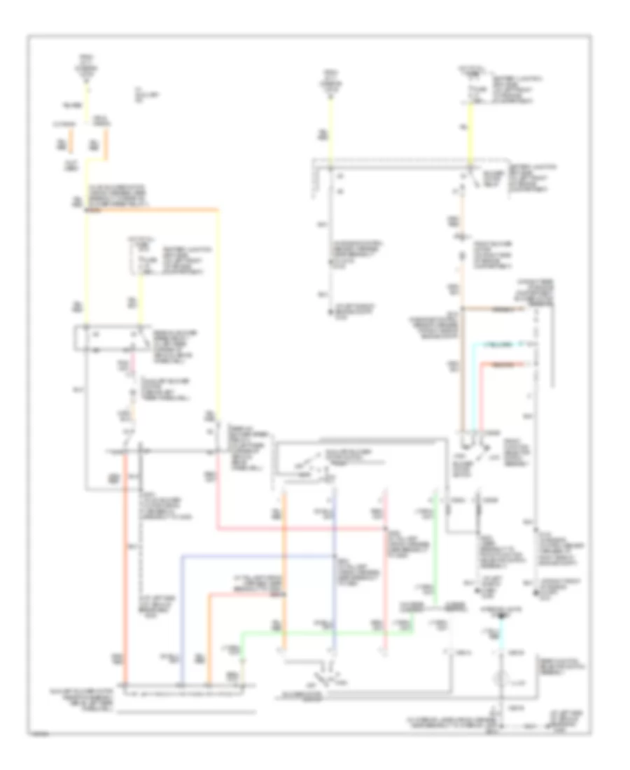
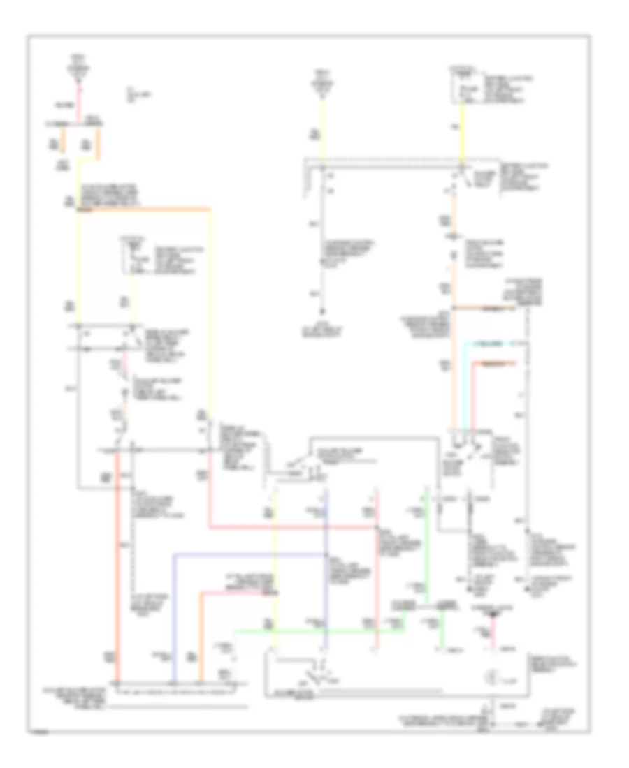
4.2L, Manual A/C Wiring Diagram, without Stripped Chassis (1 of 2) for Ford Econoline E250 2003

List of elements for 4.2L, Manual A/C Wiring Diagram, without Stripped Chassis (1 of 2) for Ford Econoline E250 2003:
- (1: temperature control potentiometer)
- (at right front of engine compt)
- (at right front of engine compt) g101
- (in engine control sensor harness, in breakout to battery junction box) s110
- (in engine control sensor harness, in breakout to battery junction box) s176
- (in fuel charge wiring harness, near breakout to intake manifold runner control module) s107
- (in window regulator relay switch harness, near breakout to ignition switch) s223
- (left side of dash) g204
- A/c clutch cycling pressure switch (in right front of engine compartment)
- A/c clutch relay
- A/c clutch solenoid (on left front of engine)
- A/c compressor clutch diode (near front of engine)
- A/c high pressure switch (in right front of engine compartment)
- A/c on input signal
- A/c relay control
- Battery junction box (bjb) (in left front of engine compartment)
- C294a
- C294d
- Central junction box (cjb) (left side of dash, near kick panel)
- Defrost
- Floor
- Front function selector switch assembly
- Fuse 10a
- Fuse 15a
- Fuse 30a
- G101
- Hot at all times
- Hot in run
- Hot in start or run
- Max a/c
- Mix
- Mode switch
- Norm a/c
- Of engine compt)
- Off
- Pcm power relay
- Pnk/ (in main wiring harness, near breakout to front function selector switch assembly) s203
- Powertrain control module (pcm) (in left rear of engine compartment, near brake master cylinder)
- Red
- S142 (in engine control sensor harness, at center rear red
- Temperature blend door actuator (behind right side of dash, on a/c heater plenum)
- To blower motor relay (diagram 2 of 2)
- To s400 (diagram 2 of 2)
- Vent
- Vent norm a/c
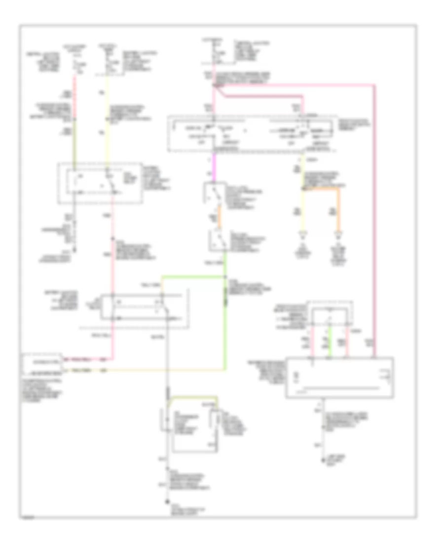
4.2L, Manual A/C Wiring Diagram, without Stripped Chassis (2 of 2) for Ford Econoline E250 2003
List of elements for 4.2L, Manual A/C Wiring Diagram, without Stripped Chassis (2 of 2) for Ford Econoline E250 2003:
- (at left side of dash) g203
- (at left side of engine compt) g100
- (at left side of vehicle rear end)
- (at left side of vehicle rear end) g400
- (at right front of engine compt) g101
- (in a/c blower motor wiring harness, near breakout to rear a/c blower speed relay 1) s400
- (in engine control sensor harness, near breakout to c219) s122
- (in interior lamps wiring harness, near breakout to interior lamp) s913
- (in right rear of engine compartment) blower motor resistor
- (in taillamp wiring harness, near breakout to c925) s303
- (not used)
- 87a
- Auxiliary blower motor (above left rear wheelwell)
- Auxiliary blower motor resistor assembly (above left rear wheelwell)
- Auxiliary blower motor switch
- Battery junction box (bjb) (in left front of engine compartment)
- Blower motor relay
- Blower motor switch
- C294b
- C294c
- C951a
- C951b
- Cutaway
- From s111 (diagram 1 of 2)
- Front blower motor (on right side of engine compartment)
- Front function selector switch assembly
- Fuse 50a
- G400
- High
- Hot at all times
- Illum
- Interior lights system
- Low
- Off
- Rear a/c blower speed relay 1 (in left rear corner of vehicle, above wheelwell)
- Rear a/c blower speed relay 2 (in left rear corner of vehicle, above wheelwell)
- Rear function selector switch assembly
- S143 (in engine control sensor harness, at right side of engine compt)
- S144 (in engine control sensor harness, at right side of engine compt)
- S202 (near breakout to front function selector switch assembly)
- S304 (in taillamp wiring harness, near breakout to c925)
- S305 (in taillamp wiring harness, near breakout to c925)
- S401 (in a/c blower motor wiring harness, in breakout to c405)
- Van & wagon
- W/ auxiliary a/c
- W/ rear control
- W/o rear control
4.6L
4.6L, Manual A/C Wiring Diagram (1 of 2) for Ford Econoline E250 2003
List of elements for 4.6L, Manual A/C Wiring Diagram (1 of 2) for Ford Econoline E250 2003:
- (1: temperature control potentiometer)
- (at right front of engine compt)
- (in engine control sensor harness, in breakout to battery junction box) s110
- (in engine control sensor harness, in breakout to battery junction box) s176
- (in window regulator relay switch harness, near breakout to ignition switch) s223
- (left side of dash) g204
- 87a
- A/c clutch cycling pressure switch (in right front of engine compartment)
- A/c clutch relay
- A/c clutch solenoid (on lower right front of engine)
- A/c compressor clutch diode (near front of engine)
- A/c high pressure switch (in right front of engine compartment)
- A/c on input sig
- A/c relay ctrl
- Battery junction box (bjb) (in left front of engine compartment)
- C294a
- C294d
- Central junction box (cjb) (left side of dash, near kick panel)
- Defrost
- Engine compartment)
- Floor
- Front function selector switch assembly
- Fuse 15a
- Fuse 30a
- G101
- G101 (at right front of engine compt)
- Hot at all times
- Hot in run
- Hot in start or run
- Max a/c
- Mix
- Mode switch
- Norm a/c
- Off
- Pcm power relay
- Pnk/ (in main wiring harness, near breakout to front function selector switch assembly) s203
- Powertrain control module (pcm) (in left rear of engine compartment, near brake master cylinder)
- Red
- S142 (in engine control sensor harness, at center rear of engine compartment)
- S166 (in engine control sensor harness, near breakout to c139)
- Temperature blend door actuator (behind right side of dash, on a/c heater plenum)
- To blower motor relay (diagram 2 of 2)
- To s400 (diagram 2 of 2)
- Vent
- Vent norm a/c
4.6L, Manual A/C Wiring Diagram (2 of 2) for Ford Econoline E250 2003
List of elements for 4.6L, Manual A/C Wiring Diagram (2 of 2) for Ford Econoline E250 2003:
- (at left side of dash) g203
- (at left side of engine compt) g100
- (at left side of vehicle rear end)
- (at left side of vehicle rear end) g400
- (at right front of engine compt) g101
- (in a/c blower motor wiring harness, near breakout to rear a/c blower speed relay 1) s400
- (in engine control sensor harness, near breakout to c219) s122
- (in interior lamps wiring harness, near breakout to interior lamp) s913
- (in right rear of engine compartment) blower motor resistor
- (in taillamp wiring harness, near breakout to c925) s303
- (not used)
- 87a
- Auxiliary blower motor (above left rear wheelwell)
- Auxiliary blower motor resistor assembly (above left rear wheelwell)
- Auxiliary blower motor switch
- Battery junction box (bjb) (in left front of engine compartment)
- Blower motor relay
- Blower motor switch
- C294b
- C294c
- C951a
- C951b
- Cutaway
- From s111 (diagram 1 of 2)
- Front blower motor (on right side of engine compartment)
- Front function selector switch assembly
- Fuse 50a
- G400
- High
- Hot at all times
- Illum
- Interior lights system
- Low
- Off
- Rear a/c blower speed relay 1 (in left rear corner of vehicle, above wheelwell)
- Rear a/c blower speed relay 2 (in left rear corner of vehicle, above wheelwell)
- Rear function selector switch assembly
- S143 (in engine control sensor harness, at right side of engine compt)
- S144 (in engine control sensor harness, at right side of engine compt)
- S202 (in main wiring harness, near breakout to front function selector switch assembly)
- S304 (in taillamp wiring harness, near breakout to c925)
- S305 (in taillamp wiring harness, near breakout to c925)
- S401 (in a/c blower motor wiring harness, in breakout to c405)
- Van & wagon
- W/ auxiliary a/c
- W/ rear control
- W/o rear control
5.4L
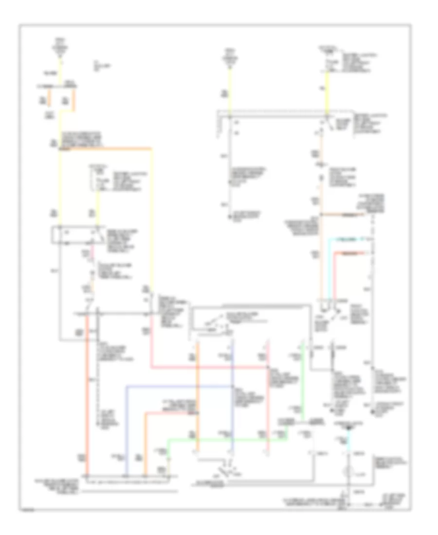
5.4L, Manual A/C Wiring Diagram, without Stripped Chassis (1 of 2) for Ford Econoline E250 2003
List of elements for 5.4L, Manual A/C Wiring Diagram, without Stripped Chassis (1 of 2) for Ford Econoline E250 2003:
- (at right front of engine compt) g101
- (in engine control sensor & fuel charge wiring harness, near breakout to a/c clutch solenoid) s189
- (in window regulator relay switch harness, near breakout to ignition switch) s223
- (left side of dash) g204
- (temperature control potentiometer)
- 5.4l, 5.4l cng & 6.8l
- 7.3l di turbo diesel
- A/c clutch cycling pressure switch (in right front of engine compartment)
- A/c clutch solenoid (on lower right front of engine)
- A/c clutch solenoid (on top left front of engine)
- A/c compressor clutch diode (near front of engine)
- A/c high pressure switch (in right front of engine compartment)
- A/c on input signal
- C294a
- C294d
- Central junction box box (cjb) (left side of dash, near kick panel)
- Defrost
- Floor
- Front function selector switch assembly
- Front function selector switch assembly front12
- Fuse 15a
- Hot in run
- Max a/c
- Mix
- Mode switch
- Norm a/c
- Off
- Pnk/ (in main wiring harness, near breakout to front function selector switch assembly) s203
- Powertrain control module (pcm) (in left rear of engine compartment, near brake master cylinder)
- S111 (in engine control sensor harness, in breakout to battery junction box)
- S141 (in engine control sensor harness, near breakout to c139) (7.3l: in engine control sensor harness, near breakout to c1168)
- S143 (in engine control sensor harness, at right side of engine compartment)
- Temperature blend door actuator (behind right side of dash, on a/c heater plenum)
- To blower motor relay (diagram 2 of 2)
- To s400 (diagram 2 of 2)
- Vent
- Vent norm a/c
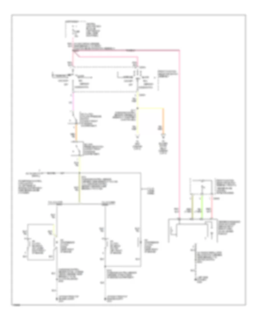
5.4L, Manual A/C Wiring Diagram, without Stripped Chassis (2 of 2) for Ford Econoline E250 2003
List of elements for 5.4L, Manual A/C Wiring Diagram, without Stripped Chassis (2 of 2) for Ford Econoline E250 2003:
- (at left side of dash) g203
- (at left side of vehicle rear end)
- (at left side of vehicle rear end) g400
- (at right front of engine compt) g101
- (in a/c blower motor wiring harness, near breakout to rear a/c blower speed relay 1) s400
- (in engine control sensor harness, near breakout to c219) s122
- (in interior lamps wiring harness, near breakout to interior lamp) s913
- (in right rear of engine compartment) blower motor resistor
- (in taillamp wiring harness, near breakout to c925) s303
- (not used)
- 87a
- Auxiliary blower motor (above left rear wheelwell)
- Auxiliary blower motor resistor assembly (above left rear wheelwell)
- Auxiliary blower motor switch
- Battery junction box (bjb) (in left front of engine compartment)
- Blower motor relay
- Blower motor switch
- C294b
- C294c
- C951a
- C951b
- Cutaway
- From s111 (diagram 1 of 2)
- Front blower motor (on right side of engine compartment)
- Front function selector switch assembly
- Fuse 50a
- G100 (at left side of engine compt)
- G400
- High
- Hot at all times
- Illum
- Interior lights system
- Low
- Off
- Rear a/c blower speed relay 1 (in left rear corner of vehicle, above wheelwell)
- Rear a/c blower speed relay 2 (in left rear corner of vehicle, above wheelwell)
- Rear function selector switch assembly
- S143 (in engine control sensor harness, at right side of engine compt)
- S144 (in engine control sensor harness, at right side of engine compt)
- S202 (near breakout to front function selector switch assembly)
- S304 (in taillamp wiring harness, near breakout to c925)
- S305 (in taillamp wiring harness, near breakout to c925)
- S401 (in a/c blower motor wiring harness, in breakout to c405)
- Van & wagon
- W/ auxiliary a/c
- W/ rear control
- W/o rear control