AIR CONDITIONING
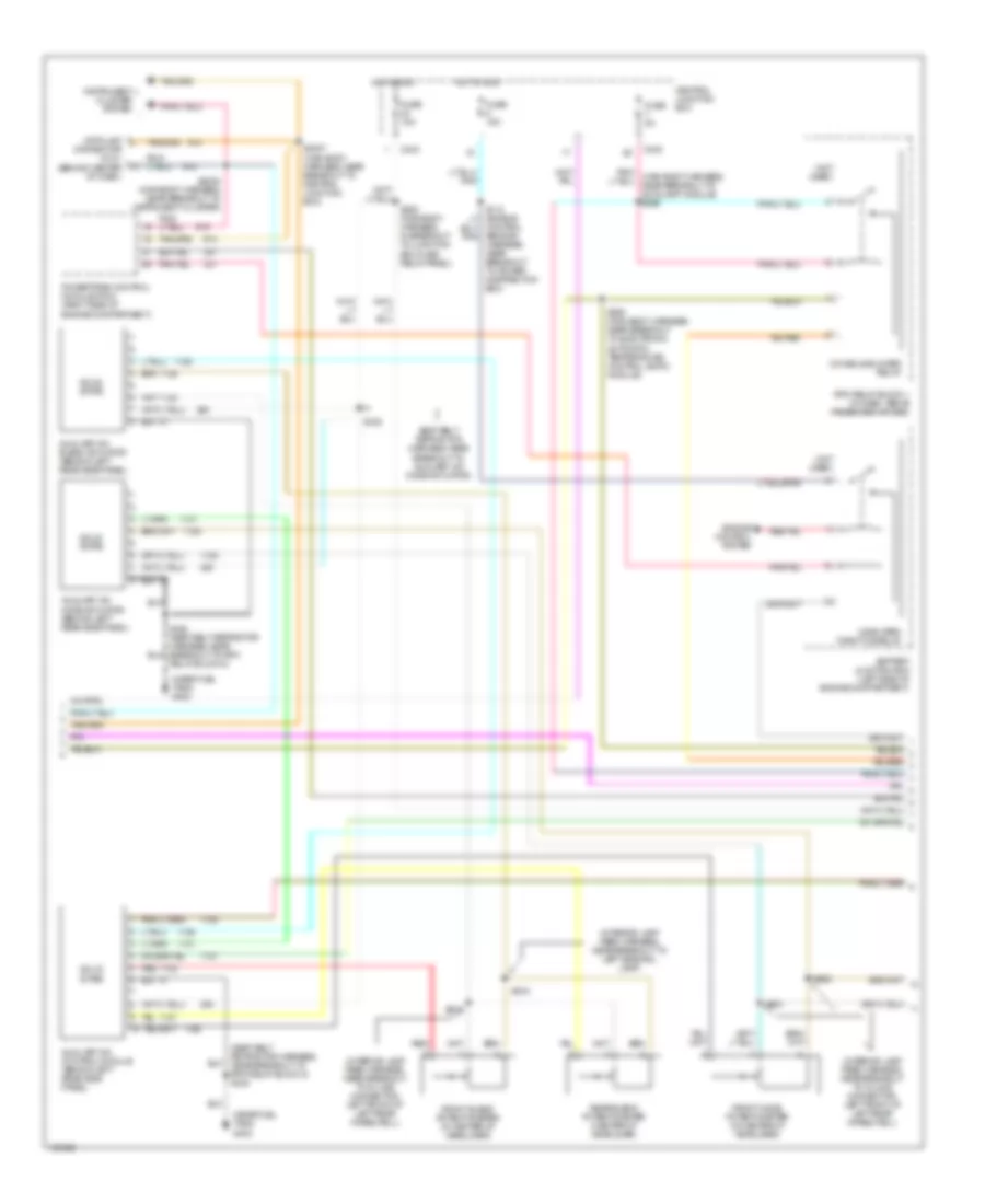
Automatic A/C Wiring Diagram (1 of 3) for Ford Expedition 1999

List of elements for Automatic A/C Wiring Diagram (1 of 3) for Ford Expedition 1999:
- (not used)
- 87a
- Amb temp sens input
- Ambient temperature sensor (left front of engine compartment)
- Audio/climate control switch assembly
- Aux rly ctrl
- Battery
- Battery junction box
- Blend door (wiper)
- Blend door 5v+
- Blend door actuator
- Blend door actuator (behind center of dash)
- Blend door gnd
- Blower ctrl out
- Blower motor (right side of engine compartment)
- Blower motor speed controller (behind right side of dash)
- Blower relay
- Blower/flasher relay block (behind center of dash)
- C205
- C242
- C243
- C280
- C281
- C282
- Central junction box
- Clockspring assembly (base of steering column)
- Data (+)
- Data (-)
- Eatc clutch rly out
- Electronic automatic temperature control (eatc) module (center of dash)
- Front panel illum
- Fuse 10a
- Fuse 5a
- Fuse 105 40a
- G200 (lower right kick panel)
- Ground
- Hot at all times
- Hot in run
- In-car temp sens
- In-car temperature sensor (behind dash)
- Inst panel lp feed
- Interior lights system
- Nca
- Power
- S200 (main body harness, near breakout to redundant steering control module)
- S203 (main body harness, near breakout to passenger airbag)
- S292 (main body harness, near breakout to electronic automatic temperature (eatc) module)
- S293 (main body harness, near breakout to electronic automatic temperature (eatc) module)
- Sensor ground
- Steering whl sw
- Sunload sens input
- Sunload sensor (top right side of dash)
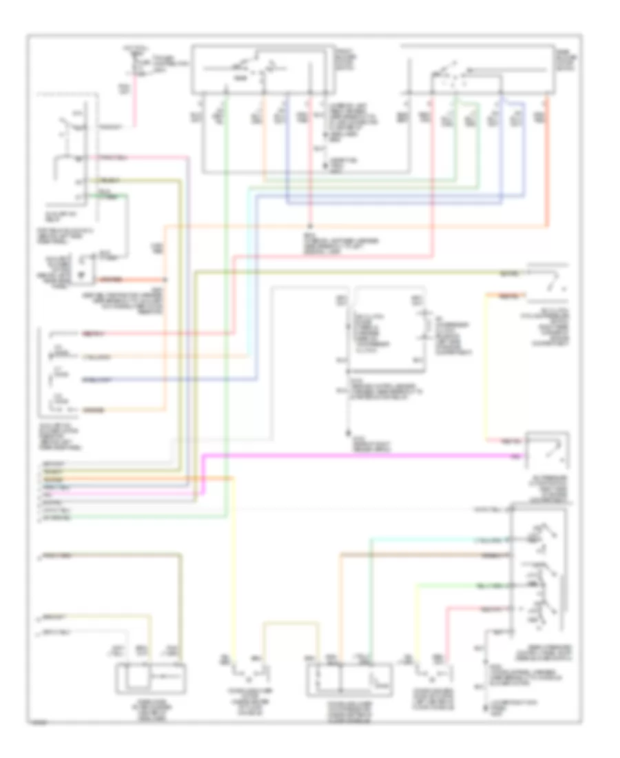
Automatic A/C Wiring Diagram (2 of 3) for Ford Expedition 1999
List of elements for Automatic A/C Wiring Diagram (2 of 3) for Ford Expedition 1999:
- (interior lamp feed harness, near breakout to in-line connector, left front of left rear wheelwell)
- (interior lamp feed harness, near breakout to left side rail lamp)
- (near fuel tank) g402
- (not used)
- (seat belt retractor harness, near breakout to rpo relay block 2) s424
- Auxiliary a/c blend actuator (behind left rear side panel)
- Auxiliary a/c control module (behind left rear side panel)
- Auxiliary a/c mode actuator (behind left rear side panel)
- Battery junction box (left side of engine compartment)
- C242
- C243
- Central junction box
- Connector (dlc) (behind center of dash)
- Console blower relay
- Control sensor harness, near breakout to power distribution box)
- Data link
- Engine control system
- Front blend potentiometer (in center of headliner)
- Front mode potentiometer (in center of headliner)
- Fuse 10a
- Fuse 15a
- Fuse 5a
- Hot in run
- Instrument cluster system
- Powertrain control module (pcm) (right side of engine compartment)
- Rear blend potentiometer (center of headliner)
- Red
- Relay block 2)
- Rpo relay block 1 (in dash, above passenger air bag)
- S2007 (main body harness, near breakout to central junction box)
- S2008 (main body harness, near breakout to instrument cluster)
- S228 (main body harness, in breakout to junction box fuse/ relay panel)
- S295 (main body harness, near breakout to electronic automatic temperature control (eatc) module)
- S422
- S918
- S919
- S920
- S921
- Seat belt retractor harness, near breakout to auxiliary a/c mode actuator)
- Solid state
- Wide open throttle relay
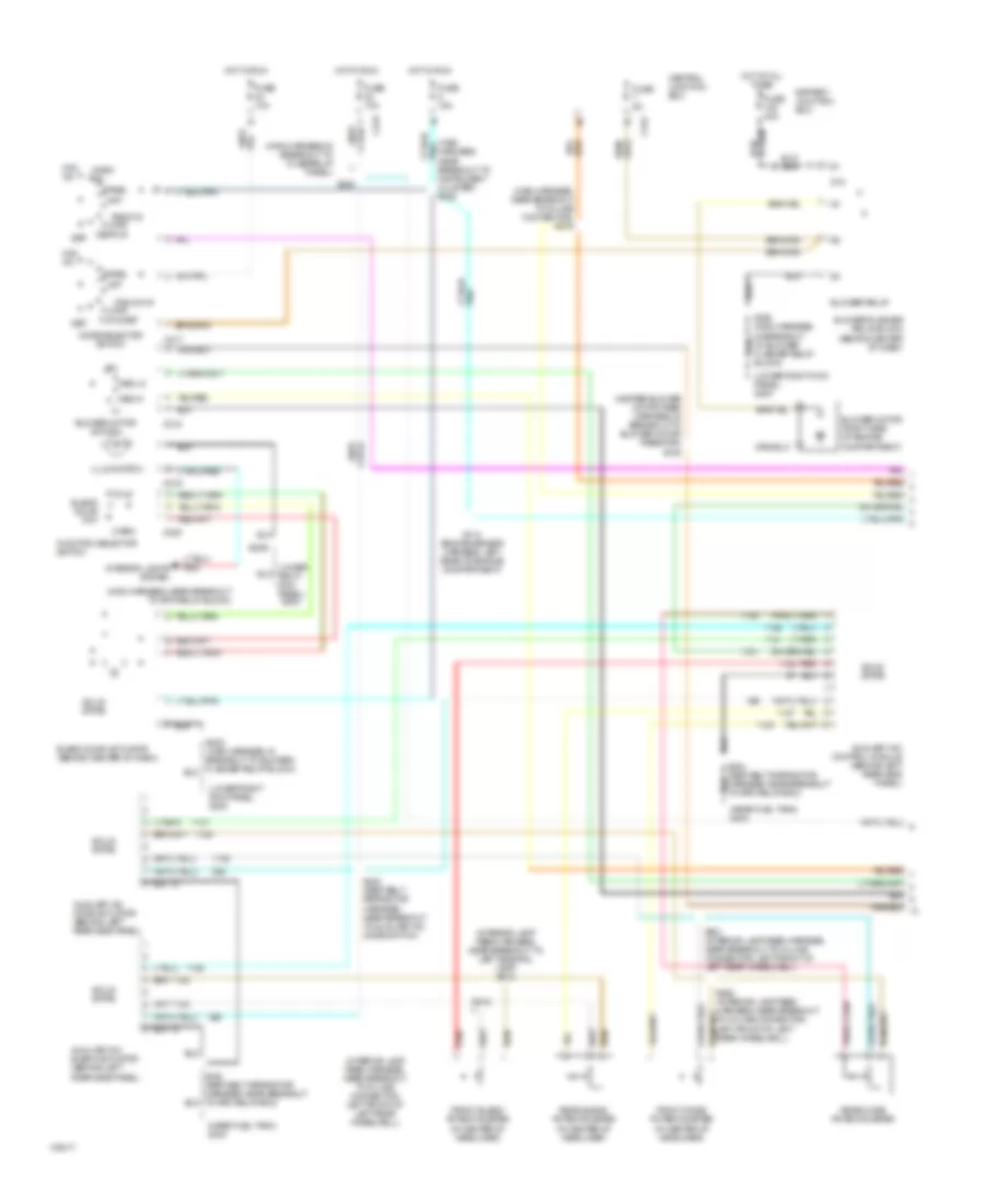
Automatic A/C Wiring Diagram (3 of 3) for Ford Expedition 1999
List of elements for Automatic A/C Wiring Diagram (3 of 3) for Ford Expedition 1999:
- (interior lamp feed harness, near breakout to in-line connector in center of headliner) s926
- (lower right kick panel) g200
- (near fuel tank) g402
- 0.6 ohms
- 0ff
- 2.7 ohms
- 3.8 ohms
- 87a
- A/c clutch cycling pressure switch (right rear corner of engine compartment)
- A/c clutch diode (taped in harness, near a/c compressor clutch)
- A/c compressor clutch solenoid (left side of engine compartment)
- A/c pressure cutoff switch (right side of engine compartment)
- Auxiliary a/c blower motor resistor (behind left rear side panel)
- Auxiliary a/c relay
- Auxiliary blower motor (behind left rear side panel)
- Console blend door actuator (left center of floor console)
- Console blower motor (inside center of floor console)
- Console blower motor resistor (inside center of floor console)
- Front blower motor switch
- Fuse 30a
- G102 (rear of right fender apron)
- Hot at all times
- Low
- Low med
- Med
- Off
- Ohms
- Power distribution box
- Rear
- Rear blower motor switch
- Rear integrated control panel (ricp) (rear blower switch)
- Rear mode potentiometer (center of headliner)
- Red/ pnk
- Red/pnk
- Rpo relay block no.2 (behind left side rear panel)
- S102 (engine control sensor harness, near breakout to starter motor relay)
- S322 (console panel harness, near breakout to console blower motor)
- S423 (seat belt retractor harness, near breakout to auxiliary a/c mode blower motor resistor)
- S916 (interior lamp feed harness, near breakout to left side rail lamp)
Manual A/C Wiring Diagram (1 of 2) for Ford Expedition 1999
List of elements for Manual A/C Wiring Diagram (1 of 2) for Ford Expedition 1999:
- (heater blower motor feed harness, in breakout to blower motor resistor) s125
- (interior lamp feed harness, near breakout to in-line connector, left front of left rear wheelwell)
- (interior lamp feed harness, near breakout to left side rail lamp) s918
- (lower right kick panel) g200
- (main harness in breakout to fuse/relay panel)
- (main harness, near breakout to in-line connector) s279
- (main harness, near breakout to instrument cluster) s222
- (main harness, near breakout to rpo relay block)
- (near fuel tank) g403
- 87a
- Auxiliary a/c blend actuator (behind left rear side panel)
- Auxiliary a/c control module (behind left rear side panel)
- Auxiliary a/c mode actuator (behind left rear side panel)
- Battery junction box
- Blend door actuator (behind center of dash)
- Blend door pot
- Blower motor (right side of engine compartment)
- Blower motor switch
- Blower relay
- Blower/flasher relay block (behind center of dash)
- C217
- C218
- C219
- C220
- C242
- C243
- Central junction box
- Cold
- Def
- Def/flr
- Floor
- Flr & def
- Front blend potentiometer (in center of headliner)
- Front mode potentiometer (in center of headliner)
- Function selector switch
- Fuse 10a
- Fuse 15a
- Fuse 40a
- Fuse 5a
- Hot at all times
- Hot in run
- Illumination
- Interior lights system
- Max a/c
- Med hi
- Med lo
- Mode selector switch
- Norm a/c
- Off
- Pan & flr
- Pan/flr
- Panel
- Pnk
- Rear blend potentiometer (in center of headliner)
- Rear mode potentiometer
- Red
- S112 (engine sensor harness, left rear of engine compartment)
- S202 (main harness, in breakout to blower/ flasher relay block)
- S203
- S228
- S422 (seat belt retractor harness, near breakout to auxiliary a/c mode switch)
- S424 (seat belt retractor harness, near breakout to rpo relay box)
- S919
- S920 (interior lamp feed harness, near breakout to in-line connector, left front of left rear wheelwell)
- S921 (interior lamp feed harness, near breakout to in-line connector, left front of left rear wheelwell)
- Solid state
- Warm
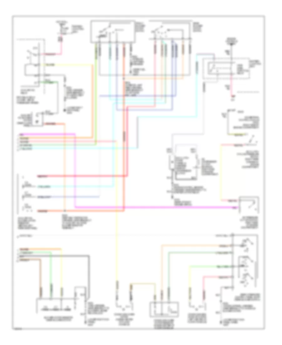
Manual A/C Wiring Diagram (2 of 2) for Ford Expedition 1999
List of elements for Manual A/C Wiring Diagram (2 of 2) for Ford Expedition 1999:
- (lower right kick panel inner) g200
- (lower right kick panel) g200
- (near fuel tank) g402
- .6 ohms
- 0.6 ohms
- 0ff
- 2.7 ohms
- 3.8 ohms
- 87a
- A/c clutch cycling pressure switch (right rear corner of engine compartment)
- A/c clutch diode (taped in harness, near a/c compressor clutch)
- A/c compressor clutch solenoid (right side of engine compartment)
- A/c pressure cut off switch (right side of engine compartment)
- Accs
- Auxiliary a/c blower motor (rear floor panel)
- Auxiliary a/c blower motor resistor (behind left rear side panel)
- Auxiliary a/c relay
- Battery junction box
- Blower motor resistor (near blower motor)
- Console blend door actuator (left center of floor console)
- Console blower motor (inside center of floor console)
- Console blower motor resistor (inside center of floor console)
- Engine controls system
- Front blower motor switch
- Fuse 30a
- G102 (rear of right fender apron)
- Hot at all times
- Med
- Nca
- Off
- Ohms
- Powertrain control module (pcm) (right side of engine compartment)
- Rear
- Rear blower motor switch
- Rear integrated control panel (ricp) (rear blower switch)
- Red/pnk
- Rpo relay box 2 (in dash, above passenger airbag)
- S202 (main harness, near breakout to blower/flasher relay block)
- S204 (main harness near breakout to instrument cluster)
- S322 (console panel harness, near breakout to console blower motor)
- S423 (seat belt retractor harness, near breakout to auxiliary a/c mode blower resistor assembly)
- S916 (interior lamp feed harness, near breakout to left side rail lamp)
- Wide open throttle relay