AIR CONDITIONING
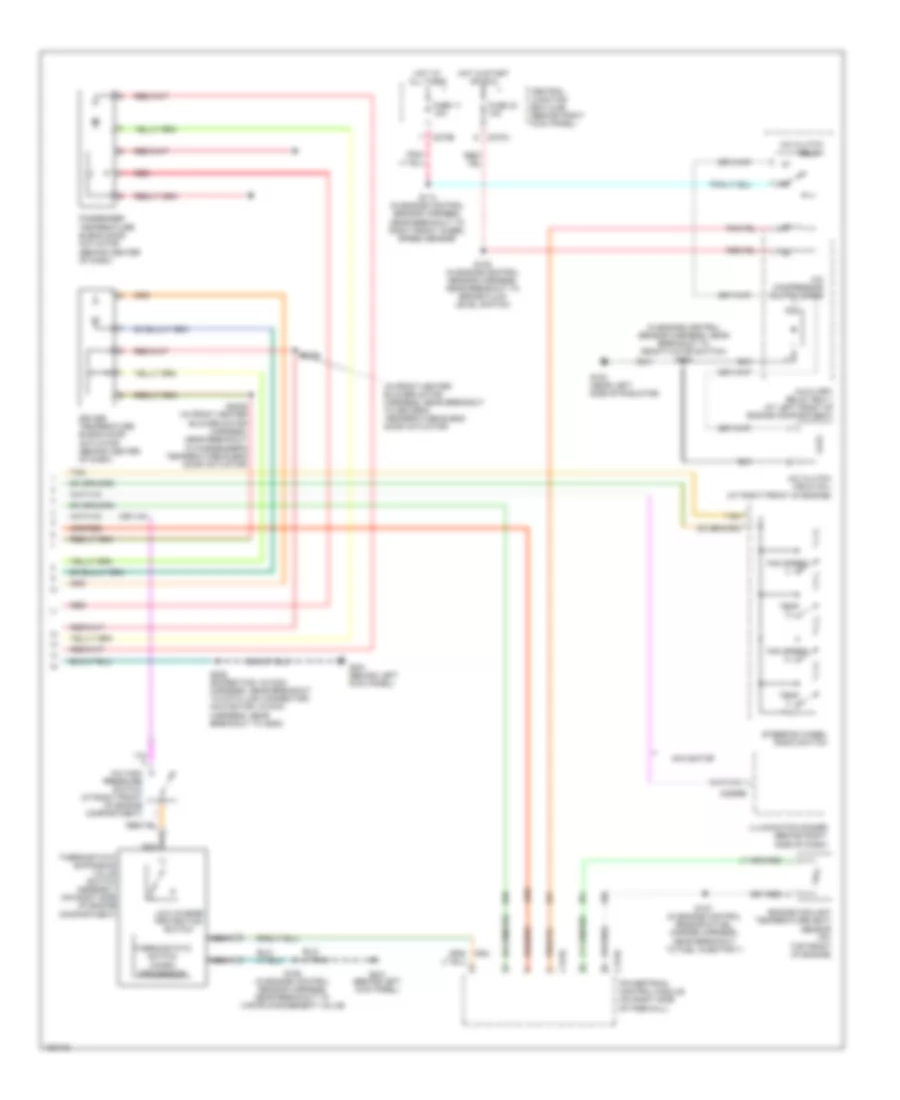
Automatic A/C Wiring Diagram (1 of 2) for Ford Expedition 2004

List of elements for Automatic A/C Wiring Diagram (1 of 2) for Ford Expedition 2004:
- (behind left kick panel) g301
- (behind right kick panel) g200
- (behind right side of dash) heater blower motor speed controller
- (expedition: near breakout to dlc) (navigator: near breakout to g202) s208
- (expedition: near breakout to electronic automatic temperature control module) (navigator: near breakout to central junction box)
- (in main harness, near breakout to glove box lamp)
- (in main harness, near breakout to illumination dimmer)
- (in main harness, near breakout to instrument cluster) s264
- (in main harness, near breakout to instrument cluster) s277
- +/-
- Air bag sliding contact (behind left side of dash)
- Ambient air temperature sensor (behind radiator grille)
- Atc solenoid & manifold assembly (behind center of dash)
- Autolamp/ sunload sensor (at top of dash)
- Auxiliary air conditioner heater circuit
- C2113b
- C228a
- C228b
- C270e
- C270g
- Central junction box (cjb) (behind right kick panel)
- Cruise control system
- Data link connector (dlc) (under left side of dash)
- Defogger system
- Electronic automatic temperature control (eatc) module (in center of dash)
- Expedition w/ dual zone eatc
- Front blower motor relay
- Fuse 116 40a
- Fuse 13 10a
- Fuse 5 7.5a
- G200 (behind right kick panel)
- Heater blower motor (behind right
- Hot at all times
- Hot in run
- If equipped
- In-vehicle temperature sensor (in left side of dash)
- In-vehicle temperature/ humidity sensor (in left side of dash)
- Interior lights system
- Microprocessor
- Navigator
- Navigator w/ dual zone eatc
- Nca
- Pate ind
- Pwr
- Red
- S2019
- S203
- S203 (in main harness, near breakout to glove box lamp)
- S241
- Side of dash)
- Sig rtn-
- Tan
- Vbatt
- Vehicle security module (vsm) (under right side of dash)
- Vpwr
- Vref
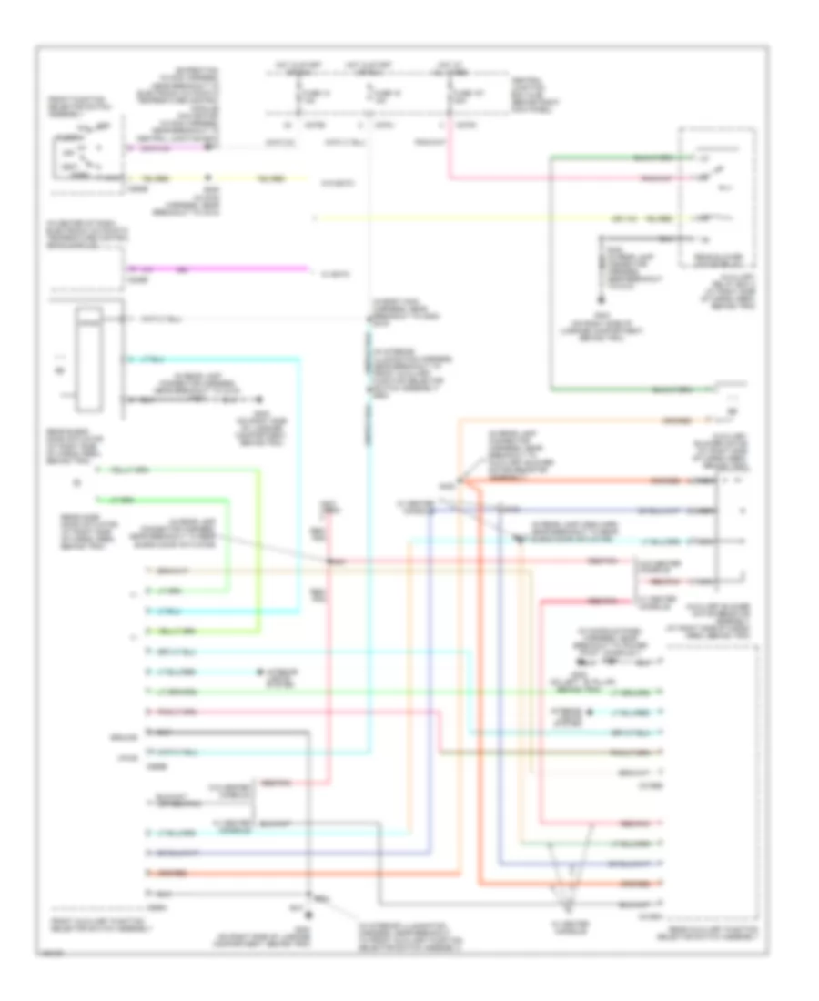
Automatic A/C Wiring Diagram (2 of 2) for Ford Expedition 2004
List of elements for Automatic A/C Wiring Diagram (2 of 2) for Ford Expedition 2004:
- (in engine control sensor harness, near breakout to deactivator switch) s104
- (in front heater blower motor harness, near breakout to driver's temperature blend door actuator)
- A/c clutch field coil (at right front of engine)
- A/c clutch relay
- A/c compressor clutch diode
- A/c high pressure switch (at right front of engine compartment)
- Auxiliary relay box 1 (at left front of engine compartment)
- C175b
- C175e
- C2065b
- C270a
- C270b
- Central junction box (cjb) (behind right kick panel)
- Driver temperature blend door actuator (behind center of dash)
- Engine coolant temperature (ect) sensor (on
- Fan speed (+)
- Fan speed (-)
- Fuse 11 10a
- Fuse 33 10a
- G100 (near left side of radiator)
- G301 (behind left kick panel)
- Hot at all times
- Hot in start or run
- Illumination dimmer (behind right side of dash)
- Low charge protection switch
- Navigator
- Nca
- Passenger temperature blend door actuator (behind center of dash)
- Powertrain control module (on right side of firewall)
- Red
- S105 (in engine control sensor harness, near breakout to brake fluid level switch)
- S106 (in engine control sensor harness, near breakout to vapor management valve)
- S113 (in engine control sensor harness, near breakout to right front wheel speed sensor)
- S127 (in engine control sensor & fuel charge harness, near breakout to fuel injector 7)
- S2025 (in front heater blower motor harness, near breakout to passenger's temperature blend door actuator)
- S2026
- S208 (expedition: in main harness, near breakout to data link connector) (navigator: in main harness, near breakout to g202)
- Steering wheel radio switch
- Tan
- Temp (+)
- Temp (-)
- Thermostatic expansion valve switch assembly (on right side of engine compartment)
- Thermostatic switch (micro- processor)
- Top front of engine)
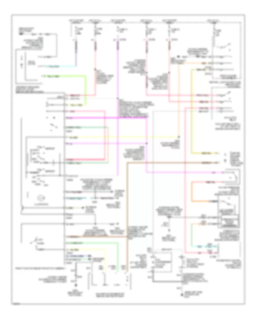
Auxiliary Heater-A/C Wiring Diagram for Ford Expedition 2004
List of elements for Auxiliary Heater-A/C Wiring Diagram for Ford Expedition 2004:
- (expedition: in main harness, near breakout to electronic automatic temperature control module) (navigator: in main harness, near breakout to central junction box) s241
- (in body main harness, near breakout to c800) s319
- (in center of dash) electronic automatic temperature control (eatc) module
- (in console panel harness, near breakout to power point, console 1) s205
- (in interior illumination harness, near breakout to front auxiliary function selector switch assembly)
- (in interior illumination harness, near breakout to front auxiliary function selector switch assembly) s903
- (in rear lamp conn harn near breakout to rear blend door actuator)
- (in rear lamp connector harness, near breakout to auxiliary blower motor resistor assembly)
- (in rear lamp connector harness, near breakout to c410) s424
- (in rear lamp connector harness, near breakout to rear blend door actuator)
- (not used)
- (on left ``b" pillar,
- +/-
- Auxiliary blower motor (at right side of cargo area, behind trim)
- Auxiliary blower motor resistor assembly (at right side of cargo area, behind trim)
- Auxiliary relay box 2 (at right side of cargo area, behind trim)
- Behind trim)
- C228b
- C270e
- C270j
- C270n
- C294b
- C3198a
- C3198b
- C989a
- C989b
- Central junction box (cjb) (behind right kick panel)
- Def
- Floor
- Front auxiliary function selector switch assembly
- Front function selector switch assembly
- Fuse 107 30a
- Fuse 13 10a
- Fuse 18 10a
- G300
- G404 (on right side of luggage compartment, behind trim)
- Ground
- Hot at all times
- Hot in start or run
- Interior lights system
- Max
- Mix
- Nca
- Near breakout to c410)
- Norm
- Off
- Rear auxiliary function selector switch assembly
- Rear blend door actuator (at right side of cargo area, behind trim)
- Rear blower motor relay
- Rear mode door actuator (at right side of cargo area, behind trim)
- Red/ pnk
- Red/pnk
- S230 (in main harness, near breakout to c210)
- S412
- S423
- S431
- S432
- S904
- Vent
- Vpwr
- W/ center console
- W/ eatc
- W/o center console
- W/o eatc
Manual A/C Wiring Diagram for Ford Expedition 2004
List of elements for Manual A/C Wiring Diagram for Ford Expedition 2004:
- (behind right kick panel) g200
- (in engine control sensor harness, near breakout to vapor management valve) s106
- (in front heater blower motor harness, in breakout to c237)
- (in front heater blower motor harness, in breakout to heater blower motor) s291
- (in main harness, near breakout to glove box lamp) s203
- (navigator: in main harness, near breakout to g202) (expedition: in main harness, near breakout to data link connector)
- (near left side of radiator) g100
- A/c clutch field coil (at right front of engine)
- A/c clutch relay
- A/c compressor clutch diode
- A/c high pressure switch (at right front of engine compartment)
- Auxiliary relay box 1 (at left front of engine compartment)
- Blower motor resistor (behind center of dash)
- C175b
- C270a
- C270b
- C270e
- C270g
- C294a
- C294b
- C294c
- Central junction box (cjb) (behind right kick panel)
- Defogger system
- Defrost
- Exterior lights system
- Floor
- Front blower motor relay
- Front function selector switch assembly
- Fuse 10a
- Fuse 11 10a
- Fuse 13 10a
- Fuse 33 10a
- Fuse 40a
- Fuse 7.5a
- G200 (behind right kick panel)
- G301 (behind left kick panel)
- Heater blower motor (behind right side of dash)
- Hot at all times
- Hot in start or run
- Illumination
- Interior lights system
- Low charge protection switch
- Max
- Mix
- Nca
- Norm
- Off
- Pnk
- Powertrain control module (on right side of firewall)
- S105 (in engine control sensor harness, near breakout to brake fluid level switch)
- S200
- S200 (in front heater blower motor harness, in breakout to c237)
- S202 (in main harness, near breakout to instrument cluster)
- S208
- S230 (in main harness, near breakout to c210)
- S241 (expedition: in main harness, near breakout to electronic automatic temperature control module) (navigator: in main harness, near breakout to central junction box)
- S262 (in main harness, near breakout to front function selector switch assembly)
- S277 (in main harness, near breakout to instrument cluster)
- Sensor harness, near breakout to deactivator switch) s104
- Solid state
- Temperature blend door actuator (behind center of dash)
- Thermostatic expansion valve switch assembly (on right side of engine compartment)
- Thermostatic switch (micro- processor)
- Vbatt
- Vent