AIR CONDITIONING
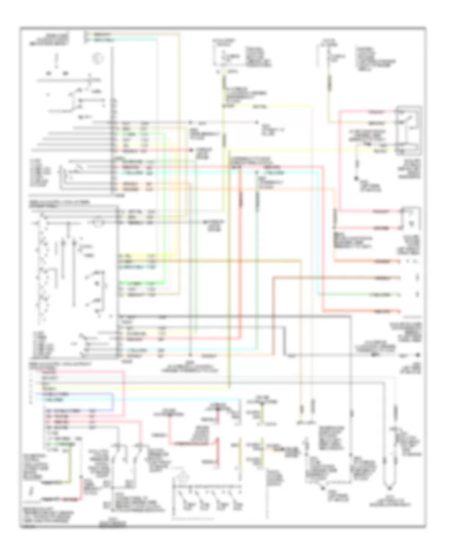
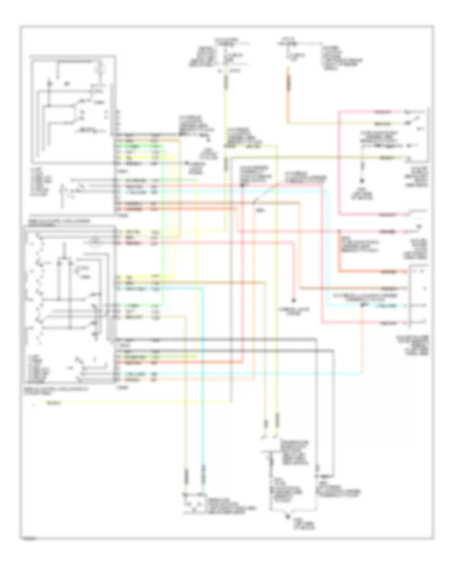
Automatic A/C Wiring Diagram (1 of 2) for Ford Explorer 2004

List of elements for Automatic A/C Wiring Diagram (1 of 2) for Ford Explorer 2004:
- (1: microprocessor)
- (2: pats indicator)
- (air conditioning harness, near breakout to temperature blend door actuator)
- (in main harness, near breakout to central junction box) s247
- (near breakout to center of dash) s219
- (near breakout to central junction box)
- A/c clutch relay
- A/c indicator diode
- Ambient air temperature sensor (right front of engine compt, near radiator support)
- Autolamp/ sunload sensor (behind glove box)
- Battery junction box (bjb) (left side of engine compt, at fender apron)
- Blower motor ctrl
- Blower motor relay
- Box lamp) g200 (at right ``a" pillar)
- C220a
- C228a
- C228b
- C270b
- C270e
- C270h
- C3203c
- Can bus+
- Can bus-
- Central junction box (cjb) (behind left side of dash)
- Computer data lines system
- Driver temperature blend door actuator (behind center of dash)
- Electronic automatic temperature control (eatc) module (behind center of dash)
- Feed back voltage
- Feedback voltage
- Front blower motor (behind center of dash)
- Front blower motor speed controller (behind center of dash)
- Fuse 10 10a
- Fuse 15 15a
- Fuse 20 5a
- Fuse 30 5a
- Fuse 36 40a
- Fuse 37 15a
- Fuse 7 15a
- G101 (left front of engine compartment)
- G206 (behind center of dash)
- G300 (at left ``a" pillar)
- Ground
- High speed signal
- Hot at all times
- Hot in run or start
- Hot in start or run
- Hot w/ rear window deforst relay energized
- Illumination
- In-vehicle temperature sensor (behind center of dash)
- Instrument cluster
- Interior lights system
- J/c 1
- J/c 2
- Left
- Micropro- cessor
- Passenger temperature blend door actuator (behind right side of dash)
- Pwr
- Remote solenoid assembly (behind center of dash)
- Right
- Rs1 recir
- Rs2 defrost
- Rs3 floor
- Rs4 panel
- Rs5 heater ctr vlv
- Rs5 heater ctrl valve
- S232
- S233 (in main harness, near breakout to data link connector)
- S242
- S243
- S317 (in window regulator jumper assembly, near breakout to left rear speaker)
- Seats system
- Sig rtn
- Signal rtn
- Twisted pair
- Var speed signal
- Vbatt
- Vehicle security module (vsm) (above right rear wheelwell)
- Vpwr
- Vref
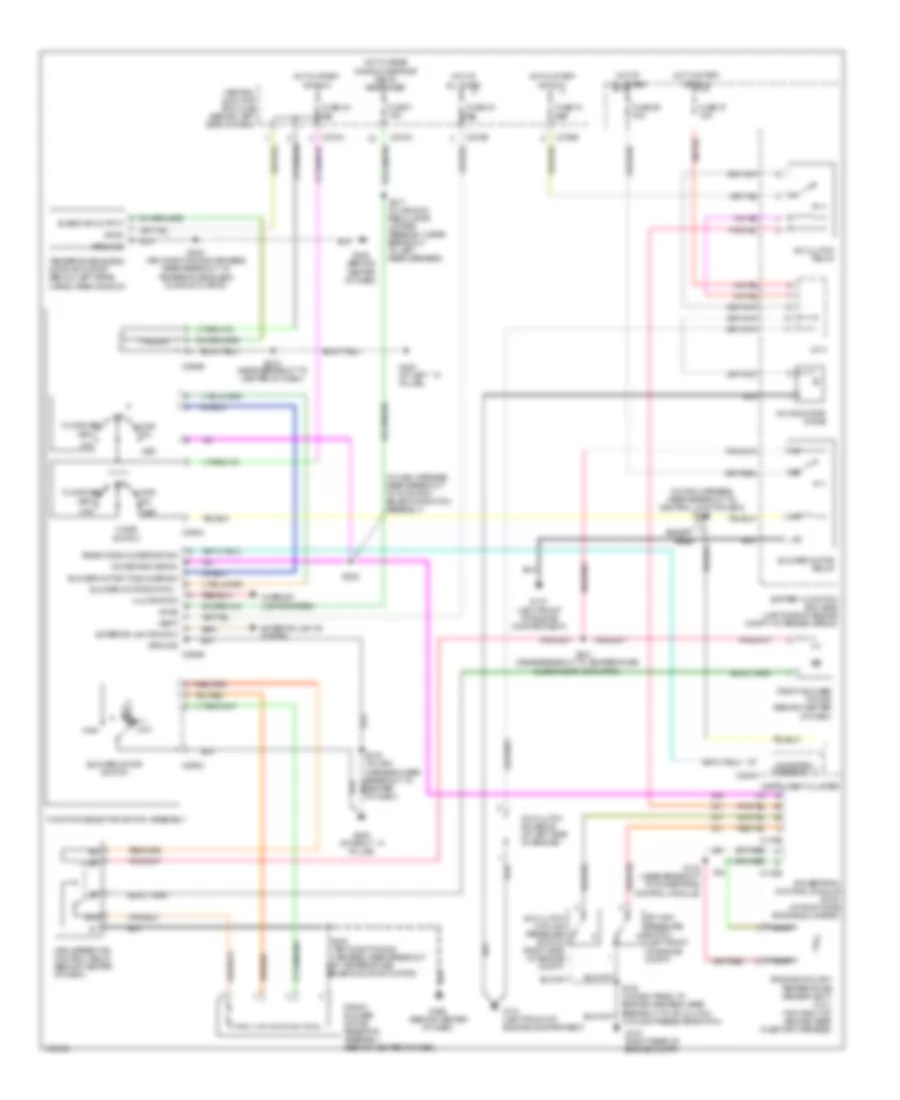
Automatic A/C Wiring Diagram (2 of 2) for Ford Explorer 2004
List of elements for Automatic A/C Wiring Diagram (2 of 2) for Ford Explorer 2004:
- (at breakout to roof opening panel switch)
- (in air conditioning harness, near breakout to c3007) s341
- (in interior illumination harness, at breakout to c340) s908
- (in interior illumination harness, near breakout to c340) s326
- 0) off 1) low 2) med low 3) med high 4) high 5) ceiling 6) floor
- 0) off 1) rear 2) low 3) med low 4) med high 5) ceiling 6) floor
- A/c clutch cycling pressure switch (right side of engine compt)
- A/c clutch solenoid (at left side of engine)
- A/c high pressure switch (left front of engine compt)
- Air bag sliding contact (at top of steering column)
- Audio/ climate control switch
- Auxiliary a/c relay (behind left side of rear seats)
- Auxiliary blower motor (left side of cargo area)
- Auxiliary blower motor resistor assembly (in left rear cargo area)
- Battery junction box (bjb) (left side of engine compt, at fender apron)
- C175b
- C175e
- C218a
- C270a
- C938a
- C938b
- C940a
- C940b
- Central junction box (cjb) (behind left side of dash)
- Cool
- Cruise control system
- Engine coolant temperature (ect) sensor (4.0l: top right of engine, near injector harness)
- Fan dn
- Fan up
- Fuse 25 5a
- Fuse 33 30a
- G101 (left front of engine compartment)
- G104 (right rear of engine compt)
- G400 (left rear of vehicle)
- G401 (at right ``d" pillar)
- Harness, at breakout to c340)
- Hot at all times
- Hot in start or run
- Interior lights system
- Nca
- Powertrain control module (pcm) (at right side engine bulkhead)
- Rear a/c control module (front) (in roof panel)
- Rear a/c control module (rear) (in roof panel)
- Rear mode door actuator (behind rear seats)
- S102 (near breakout to pcm)
- S135 (in dash panel to engine harness, near breakout to a/c clutch cycling pressure switch)
- S341 (in air conditioning harness, near breakout to c3007)
- S903 (near breakout to c340)
- S906 (in interior illumination harness, at breakout to c340)
- S907 (at breakout to c340)
- S910
- Temp dn
- Temp up
- Temperature blend door actuator (below left rear cargo area window)
- Warm
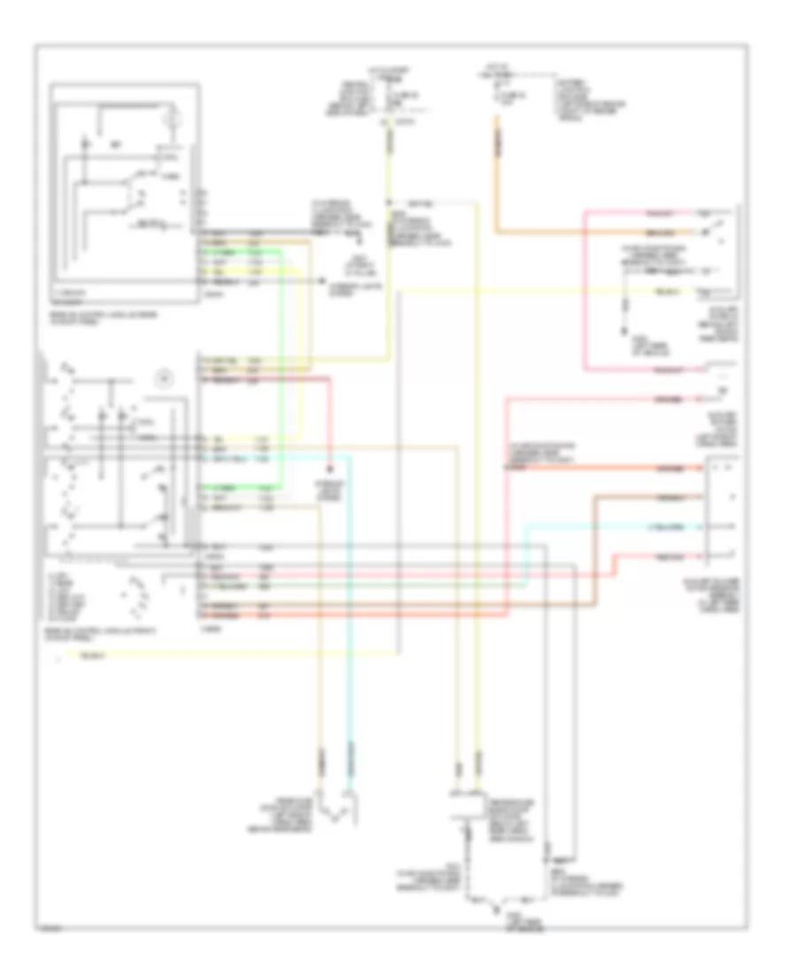
Manual A/C Wiring Diagram, with Sliding Roof (1 of 2) for Ford Explorer 2004
List of elements for Manual A/C Wiring Diagram, with Sliding Roof (1 of 2) for Ford Explorer 2004:
- (in main harness, near breakout to central junction box) s249
- (in main harness, near breakout to function selector switch assembly)
- (near breakout to temperature blend door actuator)
- 87a
- A/c clutch cycling pressure switch (right side of engine
- A/c clutch relay
- A/c clutch solenoid (at left side of engine)
- A/c demand signal
- A/c high pressure switch (left front of engine compt)
- A/c indicator diode
- Battery junction box (bjb) (left side of engine compt, at fender apron)
- Blend dr output
- Blower motor relay
- Blower motor switch
- Blower motor to blower sw
- C175b
- C175e
- C220a
- C270a
- C270b
- C270e
- C270h
- C294a
- C294b
- C294c
- Central junction box (cjb) (behind left side of dash)
- Compt)
- Def
- Engine coolant temperature sensor (ect) (4.0l) (top right of engine near injector harness)
- Except base
- Exterior lights input
- Exterior lights system
- Floor
- Floor/vent
- Front blower motor (behind center of dash)
- Front blower motor resistor assembly (behind center of dash)
- Function selector switch assembly
- Fuse 10 10a
- Fuse 16 5a
- Fuse 30 5a
- Fuse 36 40a
- Fuse 37 15a
- Fuse 7 15a
- G101 (left front of engine compartment)
- G104 (right rear of engine compt)
- G200 (at right ``a" pillar)
- G206 (behind center of dash)
- G300 (at left ``a" pillar)
- Ground
- High
- High speed fan control relay (behind center of dash)
- Hot at all times
- Hot in start or run
- Hot w/ rear window defrost relay energized
- Illumination
- Instrument cluster
- Interior lights system
- J/c 2
- Low
- Max
- Med 1
- Med 2
- Medium
- Micropro- cessor
- Mix
- Mode switch
- Nca
- Off
- Powertrain control module (pcm) (at right side engine bulkhead)
- Rear window defrost sw
- S102 (near breakout to powertrain control module)
- S219 (near breakout to center of dash)
- S222
- S240 (air conditioning harness, near breakout to temperature blend door actuator)
- S241
- S317 (in window regulator jumper assembly, near breakout to left rear speaker)
- Temperature blend door actuator (below left rear cargo area window)
- Vbatt
- Vent
- Vpwr
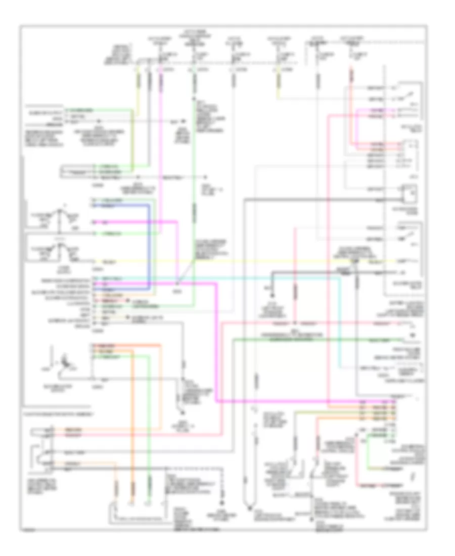
Manual A/C Wiring Diagram, with Sliding Roof (2 of 2) for Ford Explorer 2004
List of elements for Manual A/C Wiring Diagram, with Sliding Roof (2 of 2) for Ford Explorer 2004:
- (in air conditioning harness, near breakout to c3007) s339
- (in air conditioning harness, near breakout to c3007) s341
- (in interior illumination harness, near breakout to c340)
- 0) off 1) rear 2) low 3) med low 4) med high 5) ceiling 6) floor
- 1) ceiling
- 2) floor
- Auxiliary a/c relay (behind left side of rear seats)
- Auxiliary blower motor (left side of cargo area)
- Auxiliary blower motor resistor assembly (in left rear cargo area)
- Battery junction box (bjb) (left side of engine compt, at fender apron)
- C270a
- C938a
- C938b
- C940a
- Central junction box (cjb) (behind left side of dash)
- Cool
- Fuse 25 5a
- Fuse 33 30a
- G400 (left rear of vehicle)
- G401 (at right ``d" pillar)
- Hot at all times
- Hot in start or run
- Interior lights system
- Rear a/c control module (front) (in roof panel)
- Rear a/c control module (rear) (in roof panel)
- Rear mode door actuator (left side of cargo area, behind rear seats)
- S341 (in air conditioning harness, near breakout to c3007)
- S903
- S908 (in interior illumination harness, at breakout to c340)
- Temperature blend door actuator (below left rear cargo area window)
- Warm
Manual A/C Wiring Diagram, without Sliding Roof (1 of 2) for Ford Explorer 2004
List of elements for Manual A/C Wiring Diagram, without Sliding Roof (1 of 2) for Ford Explorer 2004:
- (in main harness, near breakout to central junction box) s249
- (in main harness, near breakout to function selector switch assembly)
- (near breakout to temperature blend door actuator)
- 87a
- A/c clutch cycling pressure switch (right side of engine
- A/c clutch relay
- A/c clutch solenoid (at left side of engine)
- A/c demand signal
- A/c high pressure switch (left front of engine compt)
- A/c indicator diode
- Battery junction box (bjb) (left side of engine compt, at fender apron)
- Blend dr output
- Blower motor relay
- Blower motor switch
- Blower mtr to blower switch
- C175b
- C175e
- C220a
- C270a
- C270b
- C270e
- C270h
- C294a
- C294b
- C294c
- Central junction box (cjb) (behind left side of dash)
- Compt)
- Def
- Engine coolant temperature sensor (ect) (4.0l) (top right of engine, near injector harness)
- Except base
- Exterior lights input
- Exterior lights system
- Floor
- Floor/vent
- Front blower motor (behind center of dash)
- Front blower motor resistor assembly (behind center of dash)
- Function selector switch assembly
- Fuse 10 10a
- Fuse 16 5a
- Fuse 30 5a
- Fuse 36 40a
- Fuse 37 15a
- Fuse 7 15a
- G101 (left front of engine compartment)
- G104 (right rear of engine compt)
- G200 (at right ``a" pillar)
- G206 (behind center of dash)
- G300 (at left ``a" pillar)
- Ground
- High
- High speed fan control relay (behind center of dash)
- Hot at all times
- Hot in start or run
- Hot w/ rear window defrost relay energized
- Illumination
- Instrument cluster
- Interior lights system
- J/c 2
- Low
- Max
- Med 1
- Med 2
- Medium
- Micropro- cessor
- Mix
- Mode switch
- Nca
- Off
- Powertrain control module (pcm) (at right side engine bulkhead)
- Rear window defrost sw
- S102 (near breakout to powertrain control module)
- S219 (near breakout to center of dash)
- S222
- S240 (air conditioning harness, near breakout to temperature blend door actuator)
- S241
- S317 (in window regulator jumper assembly, near breakout to left rear speaker)
- Temperature blend door actuator (below left rear cargo area window)
- Vbatt
- Vent
- Vpwr
Manual A/C Wiring Diagram, without Sliding Roof (2 of 2) for Ford Explorer 2004
List of elements for Manual A/C Wiring Diagram, without Sliding Roof (2 of 2) for Ford Explorer 2004:
- (in air conditioning harness, near breakout to c3007) s341
- (in interior illumination harness, at breakout to c340)
- (in interior illumination harness, at breakout to c340) s907
- (in interior illumination harness, near breakout to c340) s326
- (in interior illumination harness, near breakout to c340) s903
- (in pia harness, at breakout to roof opening panel switch) s910
- (left rear of vehicle)
- 0) off 1) low 2) med low 3) med high 4) high 5) ceiling 6) floor
- 0) off 1) rear 2) low 3) med low 4) med high 5) ceiling 6) floor
- Auxiliary a/c relay (behind left side of rear seats)
- Auxiliary blower motor (left side of cargo area)
- Auxiliary blower motor resistor assembly (in left rear cargo area)
- Battery junction box (bjb) (left side of engine compt, at fender apron)
- C270a
- C938a
- C938b
- C940a
- C940b
- Central junction box (cjb) (behind left side of dash)
- Cool
- Fuse 25 5a
- Fuse 33 30a
- G400
- G400 (left rear of vehicle)
- G401 (at right ``d" pillar)
- Hot at all times
- Hot in start or run
- Interior lights system
- Rear a/c control module (front) (in roof panel)
- Rear a/c control module (rear) (in roof panel)
- Rear mode door actuator (left side of cargo area, behind rear seats)
- S339 (in air conditioning harness, near breakout to c3007)
- S341 (in air conditioning harness, near breakout to c3007)
- S906
- S908 (in interior illumination harness, at breakout to c340)
- Temperature blend door actuator (below left rear cargo area window)
- Warm