AIR CONDITIONING
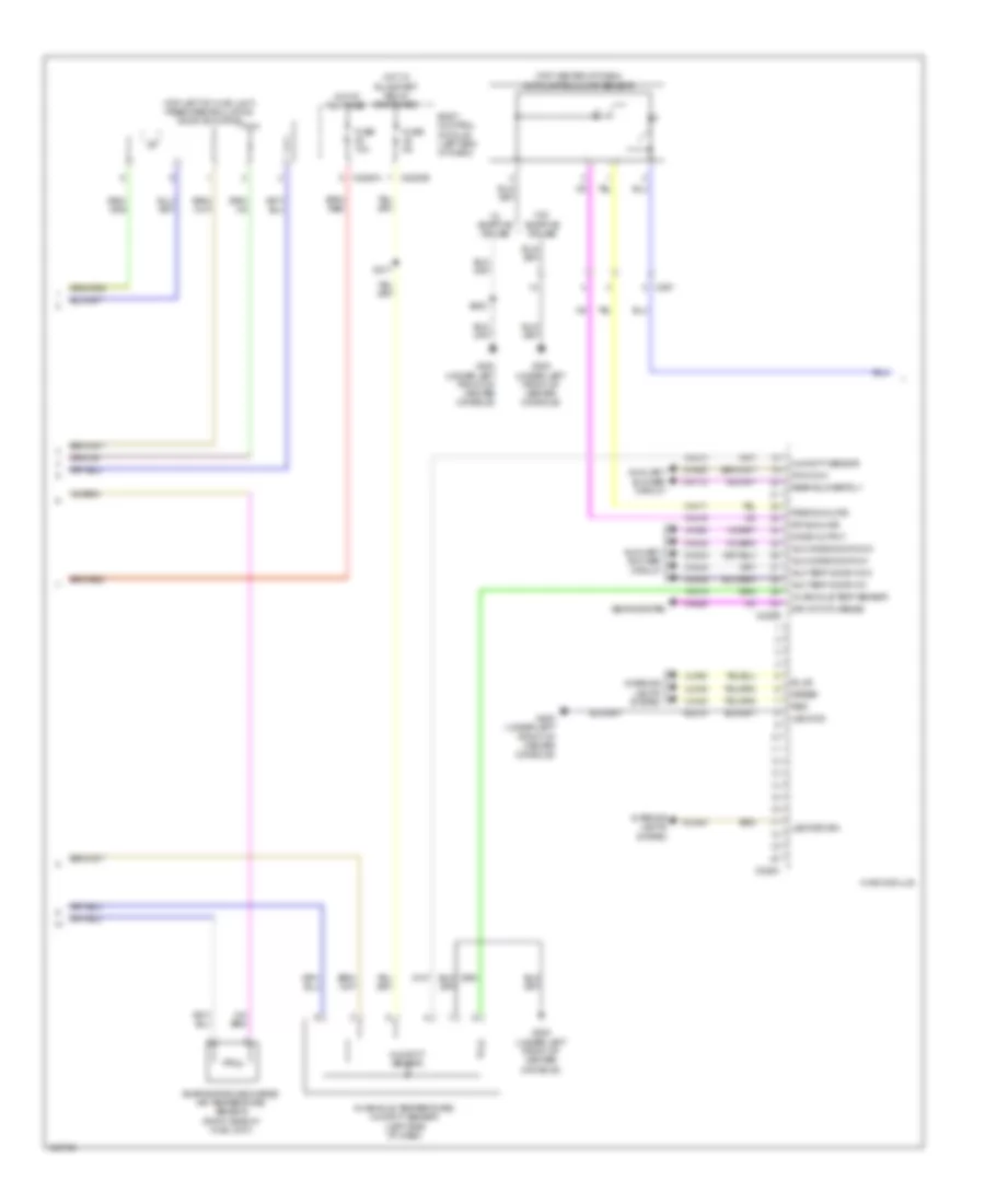
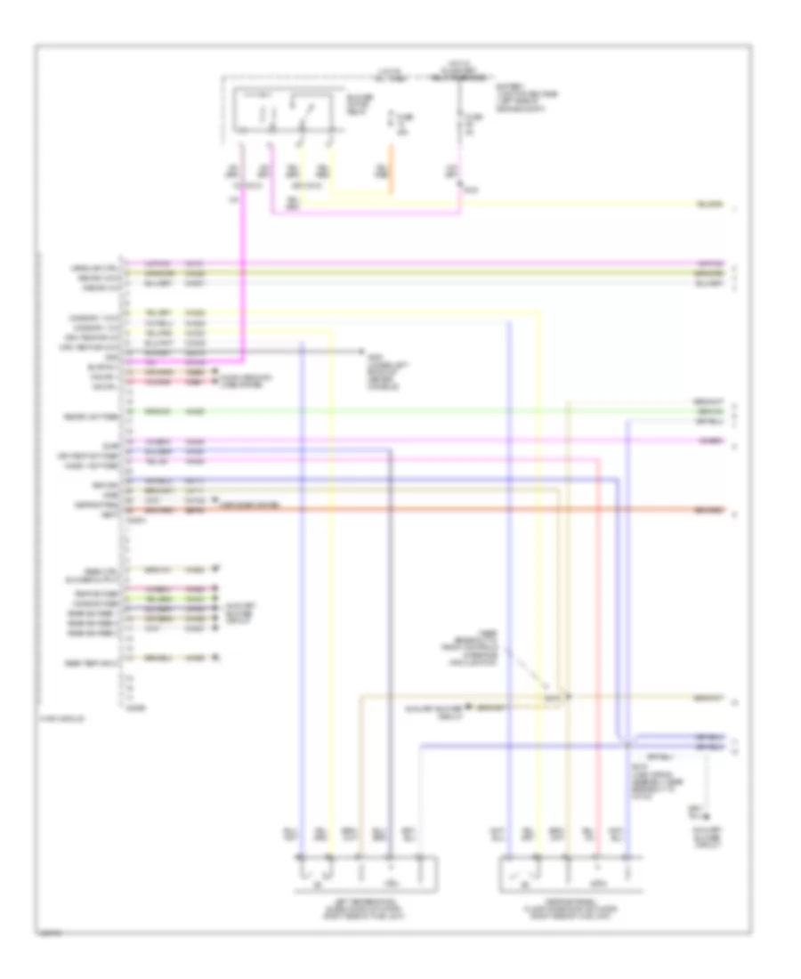
Automatic A/C Wiring Diagram (1 of 4) for Ford Explorer XLT 2014

List of elements for Automatic A/C Wiring Diagram (1 of 4) for Ford Explorer XLT 2014:
- (center of hvac unit) blower motor speed control
- (front center of hvac unit) blower motor
- (main wiring assembly, near breakout to blower motor) s229
- (main wiring assembly, near breakout to front controls interface module (fcim))
- Auxiliary blower circuit
- Battery junction box (bjb) (left side of engine compt)
- Blower motor relay
- C212
- C228a
- C228b
- C248
- Ch122
- Ch123
- Ch207
- Ch208
- Ch212
- Ch213
- Ch228
- Ch229
- Ch238
- Ch239
- Cha35
- Cha36
- Cha37
- Chs02
- Chs07
- Computer data lines system
- Defogger system
- Defrost req
- Defrost/panel/ floor mode door actuator (right side of hvac unit)
- Driv temp dr ccw
- Driv temp dr cw
- Drv heater feed
- Drv seat
- Drv temp act fdbk
- Evap
- Front blwr rly
- Fuse 30a
- Fuse 40a
- Fuse 5a
- G200 (under left front of center console)
- Gd215
- Gnd
- Hot at all times
- Hot w/ run/start relay energized
- Hvac module
- Left temperature blend door actuator (right side of hvac unit)
- Lh111
- Mode 1 act fdbk
- Mode dr 1 ccw
- Mode dr 1 cw
- Mode dr fdbk
- Mot+
- Mot-
- Ms can +
- Ms can -
- Pass heater feed
- Pass seat
- Pass st ntc sense
- Pass temp act fdbk rear ctrl blower output
- Pass temp door ccw
- Pass temp door cw
- Pwm
- Rear sig feed 1
- Rear sig feed 2
- Rear sig feed 3
- Rear temp input
- Recirc act fdbk
- Recirc ccw
- Recirc cw
- Return
- Rh111
- Right temperature blend door actuator (front center of hvac unit)
- S123
- S213
- S215
- S216 (main wiring assembly, near breakout to c2123)
- Sbb28
- Sbp46
- Seats system
- Temp dr fdbk
- Var blwr ctrl
- Vbatt
- Vdb06
- Vdb07
- Vh101
- Vh406
- Vh436
- Vh438
- Vh440
- Vh441
- Vha09
- Vha18
- Vha25
- Vha39
- Vhs27
- Vref
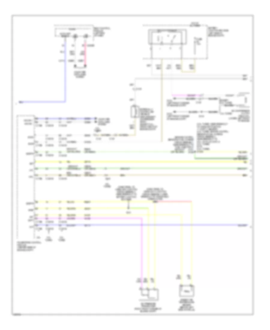
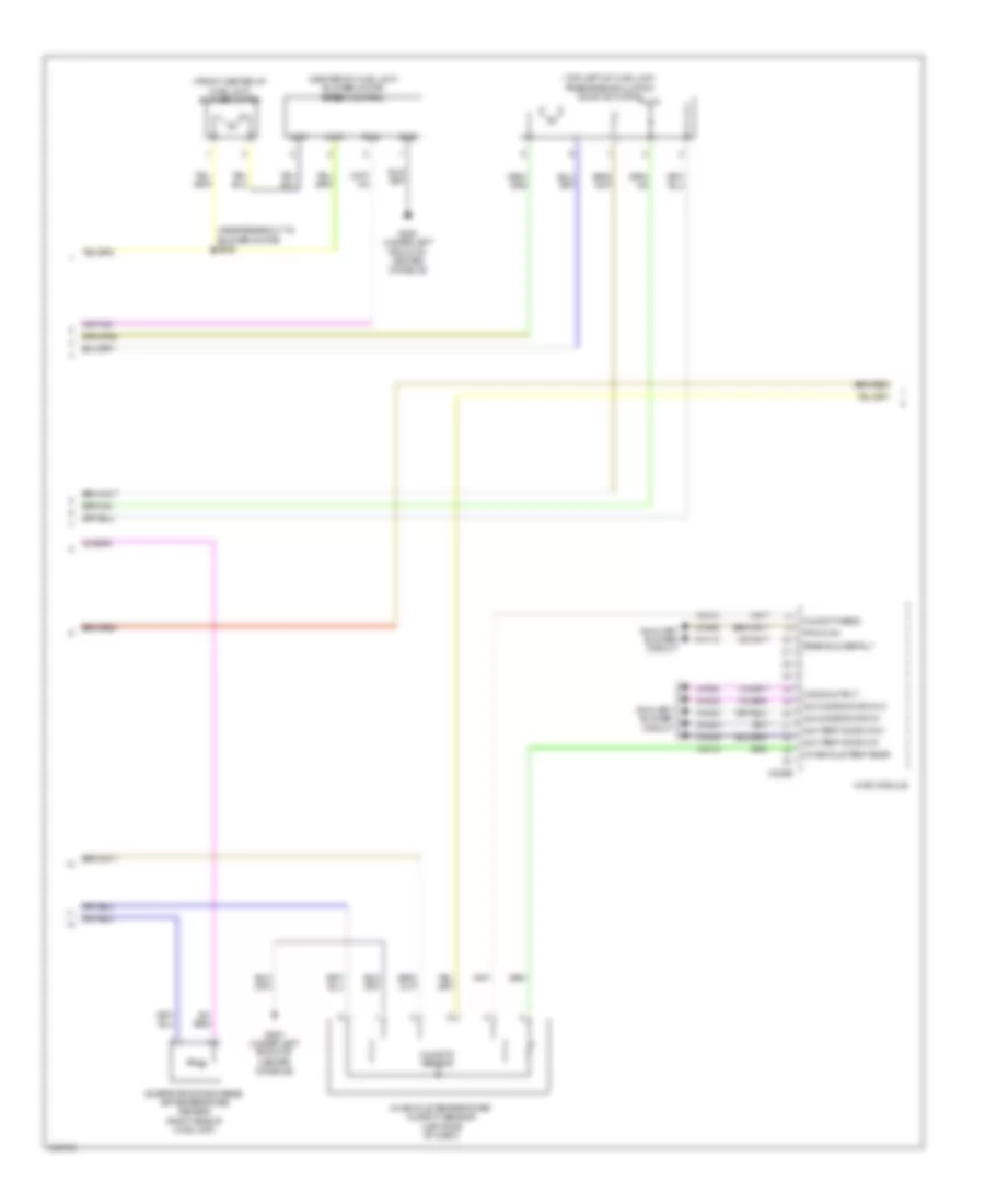
Automatic A/C Wiring Diagram (2 of 4) for Ford Explorer XLT 2014
List of elements for Automatic A/C Wiring Diagram (2 of 4) for Ford Explorer XLT 2014:
- (top center of dash) autolamp/sunload sensor
- (top left of hvac unit) fresh/recirculation door actuator
- Aux mode door ccw
- Aux mode door cw
- Aux temp door ccw
- Aux temp door cw
- Auxiliary blower circuit
- Body control module (left end of dash)
- C2280a
- C2280b
- C228b
- C228c
- C291
- Ch112
- Ch242
- Ch243
- Ch244
- Ch245
- Cha05
- Dr sunload
- Drv st ntc sense
- Evaporator discharge air temperature sensor (right side of hvac unit)
- Fuse 10a
- Fuse 5a
- G200 (under left front of center console)
- Gd215
- Green
- Hot at all times
- Hot w/ run/start relay energized
- Humidity sensor
- Hvac module
- In-vehicle temp sensor
- In-vehicle temperature/ humidity sensor (left side of dash)
- Interior lights system
- Led gnd
- Led return
- Mode output
- Pass sunload
- Pwm com
- Rear blower rly
- Red
- Rln44
- S200
- S217
- Seats system
- Vh413
- Vh414
- Vh416
- Vh417
- Vha38
- Vhs26
- Vln48
- Vln49
- Vln50
- W/ adaptive cruise
- W/o adaptive cruise
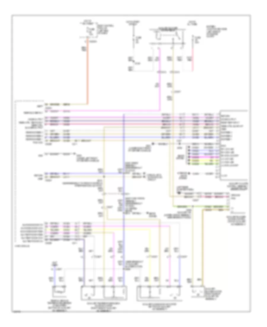
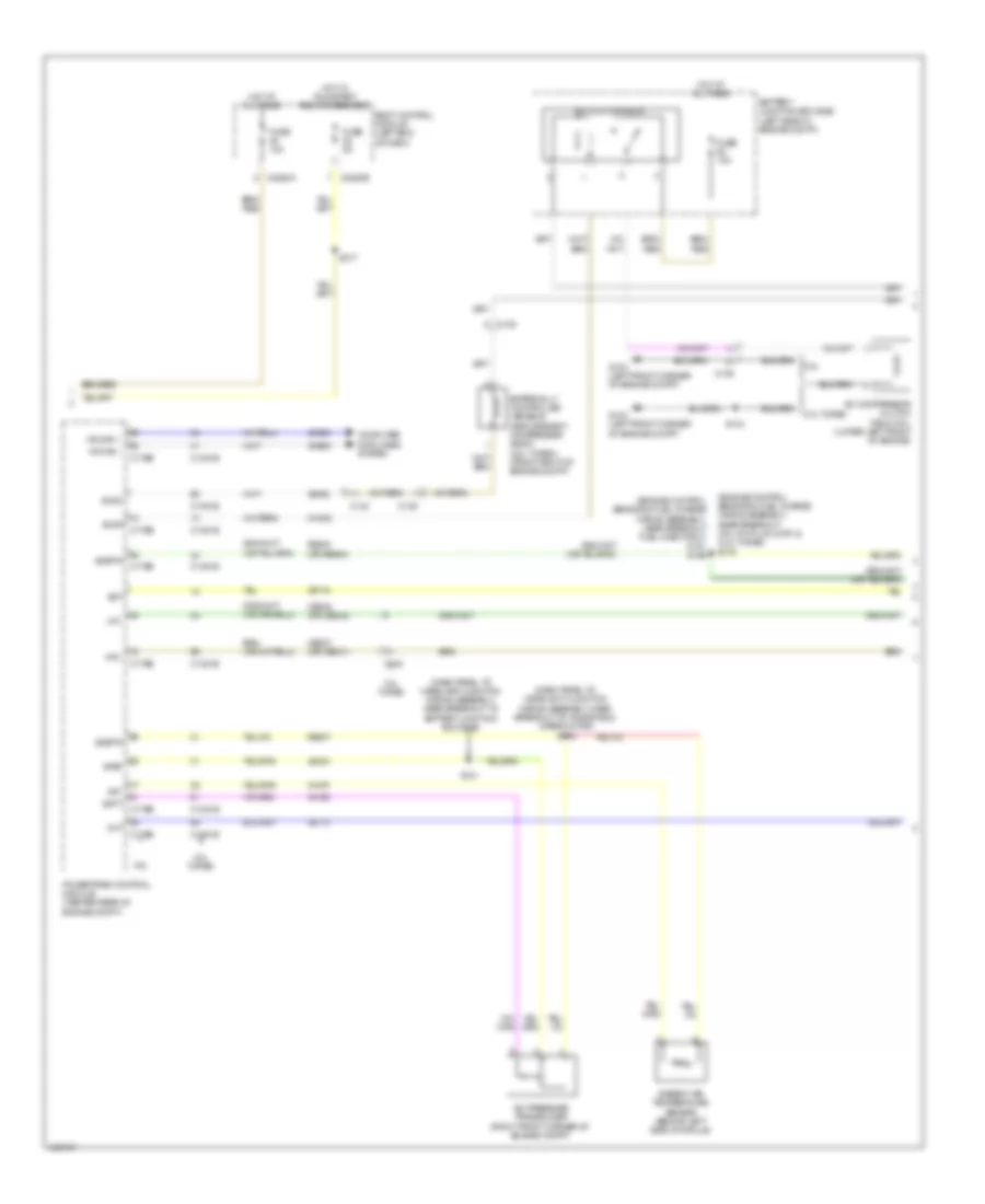
Automatic A/C Wiring Diagram (3 of 4) for Ford Explorer XLT 2014
List of elements for Automatic A/C Wiring Diagram (3 of 4) for Ford Explorer XLT 2014:
- (3.5l turbo: near breakout to camshaft position 11 (cmp11) sensor) (2.0l turbo: engine control sensor & fuel charge wiring assembly, near breakout to coil on plug (cop) 2) (2.0l turbo) s176 (3.5l turbo) s1006
- (dash panel to headlamp junction wiring assembly, near breakout to battery junction box (bjb))
- (dash panel to headlight junction wiring assembly, near breakout to windshield wiper motor) s143
- (engine control sensor & fuel charge wiring assembly, near breakout to fuel injector 3) (3.5l) s156
- 2.0l turbo
- 3.5l
- 3.5l turbo
- A/c clutch relay
- A/c compressor clutch field coil (lower left front of engine)
- A/c pressure transducer (right front corner of engine compt)
- Aat
- Accr
- Acpt
- Ambient air temperature sensor (behind left side of grille)
- Autolamp sens in
- Battery junction box (bjb) (left side of engine compt)
- Body control module (left end of dash)
- C1381b
- C1381e
- C139
- C140
- C1551b
- C1551e
- C175b
- C175e
- C2280b
- Cec07 (or cec01)
- Cec08 (or cec02)
- Ch302
- Cht
- Computer data lines system
- Ect
- Evdc
- Except 2.0l turbo
- Externally controlled variable displacement compressor (evdc) (except 3.5l) (front right of engine compt)
- Fuse 10a
- G103 (left front corner of engine compt)
- Hfc
- Hot at all times
- Hs can +
- Hs can -
- Le424
- Lfc
- Micro
- Ms can+
- Ms can-
- Powertrain control module (center rear of engine compt)
- Re405 (or re454)
- Re407
- S104
- S121
- Sigrtn
- Vdb04
- Vdb05
- Vdb06
- Vdb07
- Ve462
- Ve712
- Ve716
- Vh407
- Vh433
- Vlf14
- Vref
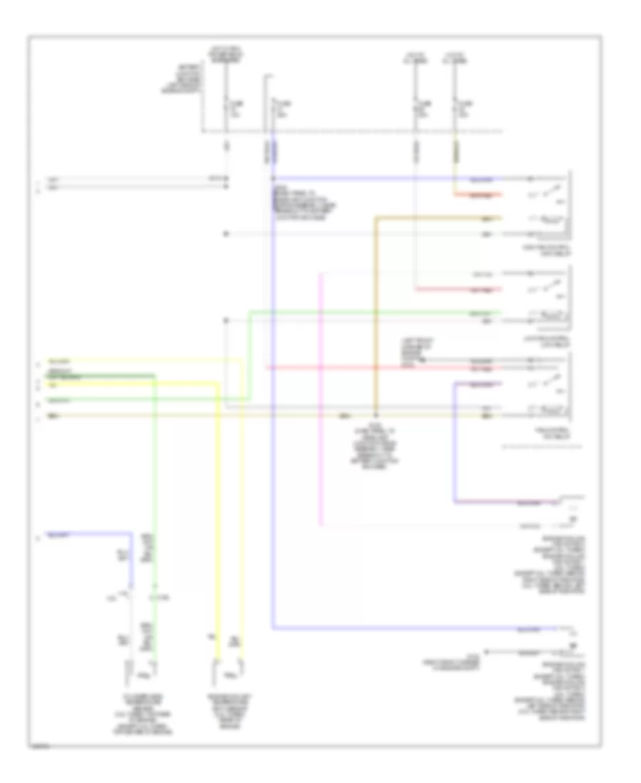
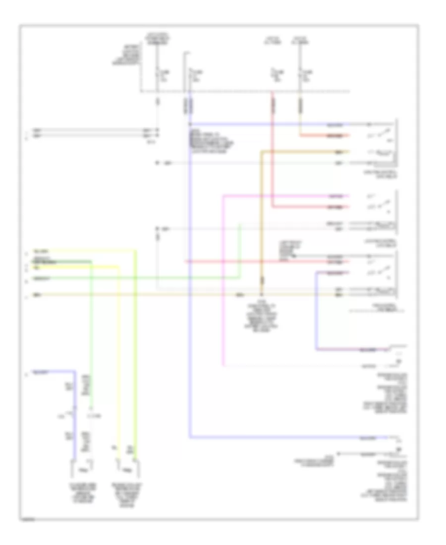
Automatic A/C Wiring Diagram (4 of 4) for Ford Explorer XLT 2014
List of elements for Automatic A/C Wiring Diagram (4 of 4) for Ford Explorer XLT 2014:
- (left front corner of engine compt) g103
- 3.5l
- Battery junction box (bjb) (left side of engine compt)
- C192
- Cylinder head temperature sensor (3.5l turbo: top rear of engine) (except 3.5l turbo: top center of engine)
- Engine coolant temperature (ect) sensor (2.0l turbo) (rear of engine)
- Engine cooling fan motor 1 (except 2.0l turbo) engine cooling fan motor 2 (2.0l turbo) (except 2.0l turbo: behind left side of radiator) (2.0l turbo: behind right side of radiator)
- Engine cooling fan motor 2 (except 2.0l turbo) engine cooling fan motor 1 (2.0l turbo) (except 2.0l turbo: behind right side of radiator) (2.0l turbo: behind left side of radiator)
- Fan control (fc) relay
- Fuse 10a
- Fuse 25a
- Fuse 40a
- G102 (right front corner of engine compt)
- High fan control (hfc) relay
- Hot at all times
- Hot w/ pcm power relay energized
- Low fan control (lfc) relay
- S113
- S182 (dash panel to headlamp junction wiring assembly, near breakout to battery junction box (bjb))
Auxiliary Blower Wiring Diagram for Ford Explorer XLT 2014
List of elements for Auxiliary Blower Wiring Diagram for Ford Explorer XLT 2014:
- (+)
- (-)
- (body main wiring assembly, near breakout to g300) (w/ heated seats) s313
- (left rear quarter panel) g301
- (main wiring assembly, near breakout to c2123) s216
- (near breakout to auxiliary blower motor) s385
- (not used)
- Aux mode door ccw
- Aux mode door cw
- Aux mode door fdbk
- Aux temp door ccw
- Aux temp door cw
- Aux temp door fdbk
- Auxiliary blower motor (right side of auxiliary a/c assembly)
- Auxiliary blower motor control (top of auxiliary a/c assembly)
- Auxiliary blower motor relay
- Auxiliary climate control assembly (except police)
- Auxiliary mode door actuator (bottom of auxiliary a/c assembly)
- Auxiliary temperature blend door actuator (right side of auxiliary a/c assembly)
- Battery junction box (bjb) (left side of of engine compt)
- Body control module (left end of dash)
- C211
- C212
- C213
- C2280a
- C228a
- C228b
- C237
- C3007
- Ch112
- Ch242
- Ch243
- Ch244
- Ch245
- Cha02
- Cha05
- Cha35
- Cha36
- Cha37
- Chs46
- Chs48
- Chs49
- Chs50
- Chs52
- Chs53
- Fuse 10a
- Fuse 40a
- Fuse 5a
- G200 (under left front of center console)
- G201 (under right front of center console)
- Gd149
- Gd214
- Gd215
- Gnd
- Ground
- Hot at all times
- Hot in start or run
- Hvac module
- Illum
- Interior lights system
- Lh high led
- Lh low led
- Lh sys lo/hi/off
- Lh111
- Manual a/c & automatic a/c circuit
- Mode output
- Pwm
- Pwm com
- Rear blower rly
- Rear ctrl blwr o/p
- Rear ctrl temp input rear ctrl blower output
- Rear in-vehicle temperature sensor (if equipped) (bottom of auxiliary a/c assembly)
- Rear sig feed 1
- Rear sig feed 2
- Rear sig feed 3
- Rear temp input
- Return
- Rh high led
- Rh low led
- Rh sys lo/hi/off
- Rh111
- S125
- S215 (near breakout to front controls interface module (fcim))
- S386 (auxiliary a/c jumper wiring assembly, near breakout c3002)
- S392
- Sbp46
- Seats system
- Sig feed 1
- Sig feed 2
- Sig feed 3
- Vbatt
- Vha09
- Vha18
- Vha19
- Vha25
- Vha38
- Vha39
- Vln04
- Vref
Manual A/C Wiring Diagram (1 of 4) for Ford Explorer XLT 2014
List of elements for Manual A/C Wiring Diagram (1 of 4) for Ford Explorer XLT 2014:
- (near breakout to front controls interface module (fcim))
- Auxiliary blower circuit
- Battery junction box (bjb) (left side of engine compt)
- Blower motor relay
- Blwr rly
- C212
- C228a
- C228b
- Ch122
- Ch123
- Ch207
- Ch208
- Ch228
- Ch229
- Ch238
- Ch239
- Cha35
- Cha36
- Cha37
- Computer data lines system
- Defogger system
- Defrost req
- Defrost/panel/ floor mode door actuator (right side of hvac unit)
- Driv temp dr ccw
- Driv temp dr cw
- Drv temp act fdbk
- Evap
- Fuse 40a
- Fuse 5a
- G200 (under left front of center console)
- Gd215
- Gnd
- Hot at all times
- Hot w/ run/start relay energized
- Hvac module
- Left temperature blend door actuator (right side of hvac unit)
- Lh111
- Mode 1 act fdbk
- Mode dr 1 ccw
- Mode dr 1 cw
- Mode dr fdbk
- Ms can +
- Ms can -
- Rear ctrl blower output
- Rear sig feed 1
- Rear sig feed 2
- Rear sig feed 3
- Rear temp input
- Recirc act fdbk
- Recirc ccw
- Recirc cw
- Return
- Rh111
- S123
- S215
- S216 (main wiring assembly, near breakout to c2123)
- Sbp46
- Temp dr fdbk
- Var blwr ctrl
- Vbatt
- Vdb06
- Vdb07
- Vh101
- Vh406
- Vh436
- Vh438
- Vh440
- Vha09
- Vha18
- Vha25
- Vha39
- Vref
Manual A/C Wiring Diagram (2 of 4) for Ford Explorer XLT 2014
List of elements for Manual A/C Wiring Diagram (2 of 4) for Ford Explorer XLT 2014:
- (center of hvac unit) blower motor speed control
- (front center of hvac unit) blower motor
- (near breakout to blower motor) s229
- (top left of hvac unit) fresh/recirculation door actuator
- Aux mode door ccw
- Aux mode door cw
- Aux temp door ccw
- Aux temp door cw
- Auxiliary blower circuit
- C228b
- Ch112
- Ch242
- Ch243
- Ch244
- Ch245
- Cha05
- Evaporator discharge air temperature sensor (right side of hvac unit)
- G200 (under left front of center console)
- Gnd
- Humidity sens
- Humidity sensor
- Hvac module
- In-vehicle temp snsr
- In-vehicle temperature/ humidity sensor (left side of dash)
- Mode output
- Mot+
- Mot-
- Pwm
- Pwm com
- Rear blower rly
- Vh413
- Vh414
- Vha38
Manual A/C Wiring Diagram (3 of 4) for Ford Explorer XLT 2014
List of elements for Manual A/C Wiring Diagram (3 of 4) for Ford Explorer XLT 2014:
- (dash panel to headlamp junction wiring assembly, near breakout to battery junction box (bjb))
- (dash panel to headlight junction wiring assembly, near breakout to windshield wiper motor) s143
- (engine control sensor & fuel charge wiring assembly, near breakout coil on plug (cop) 2) (2.0l turbo) s176
- (engine control sensor & fuel charge wiring assembly, near breakout fuel injector 3) (3.5l) s156
- 2.0l turbo
- 3.5l
- A/c clutch relay
- A/c compressor clutch field coil (lower left front of engine)
- A/c pressure transducer (right front corner of engine compt)
- Aat
- Accr
- Acpt
- Ambient air temperature sensor (behind left side of grille)
- Battery junction box (bjb) (left side of engine compt)
- Body control module (left end of dash)
- C1381b
- C1381e
- C139
- C140
- C175b
- C175e
- C2280a
- C2280b
- Cec07 (or cec01)
- Cec08 (or cec02)
- Ch302
- Cht
- Computer data lines system
- Ect
- Evdc
- Externally controlled variable displacement compressor (evdc) (2.0l turbo) (front right of engine compt)
- Fuse 10a
- Fuse 5a
- G103 (left front corner of engine compt)
- Hfc
- Hot at all times
- Hot w/ run/start relay energized
- Hs can +
- Hs can -
- Le424
- Lfc
- Powertrain control module (center rear of engine compt)
- Re405 (or re454)
- Re407
- S104
- S121
- S217
- Sigrtn
- Vdb04
- Vdb05
- Ve462
- Ve712
- Ve716
- Vh407
- Vh433
- Vref
Manual A/C Wiring Diagram (4 of 4) for Ford Explorer XLT 2014
List of elements for Manual A/C Wiring Diagram (4 of 4) for Ford Explorer XLT 2014:
- (left front corner of engine compt) g103
- 3.5l
- Battery junction box (bjb) (left side of engine compt)
- C192
- Cylinder head temperature sensor (top center of engine)
- Engine coolant temperature (ect) sensor (2.0l turbo) (rear of engine)
- Engine cooling fan motor 1 (3.5l) engine cooling fan motor 2 (2.0l turbo) (3.5l: behind left side of radiator) (2.0l turbo: behind right side of radiator)
- Engine cooling fan motor 2 (3.5l) engine cooling fan motor 1 (2.0l turbo) (3.5l: behind right side of radiator) (2.0l turbo: behind left side of radiator)
- Fan control (fc) relay
- Fuse 10a
- Fuse 25a
- Fuse 40a
- G102 (right front corner of engine compt)
- High fan control (hfc) relay
- Hot at all times
- Hot w/ pcm power relay energized
- Low fan control (lfc) relay
- S113
- S182 (dash panel to headlamp junction wiring assembly, near breakout to battery junction box (bjb))