AIR CONDITIONING
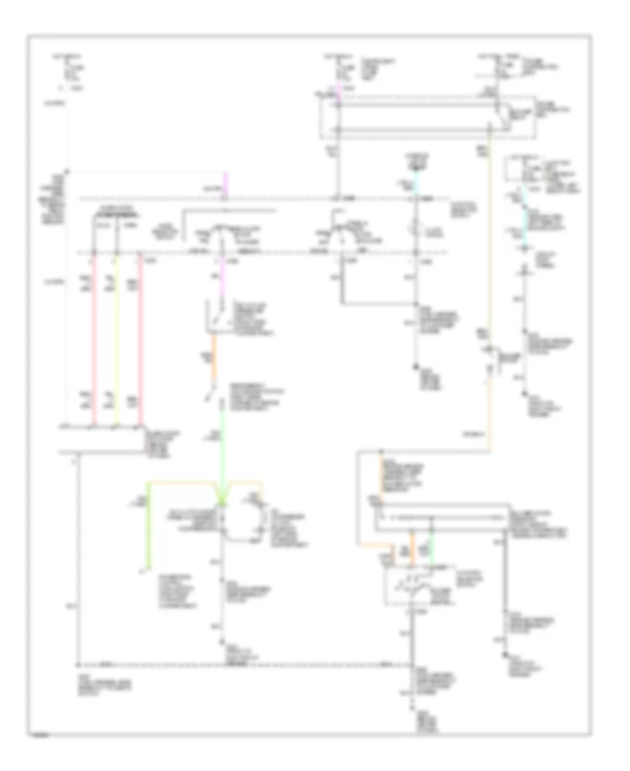
Heater Wiring Diagram for Ford F450 Super Duty 1999

List of elements for Heater Wiring Diagram for Ford F450 Super Duty 1999:
- (engine sensor harness, near breakout to blower motor resistor)
- (right side of engine compartment, near battery) g108
- (under center of dash) g201
- Blend door actuator (behind center of dash)
- Blend door potentiometer
- Blower motor
- Blower motor resistor (right side of engine compartment, near blower motor)
- Blower motor switch
- Blower relay
- C220
- C242
- C243
- C260
- C296
- C298
- Cold
- Def
- Floor
- Flr & def
- Function selector switch
- Fuse 10a
- Fuse 40a
- Hot at all times
- Hot in run
- Illumi- nation
- Instrument panel fuse box
- Interior lights system
- Mode selector switch
- Off
- Panel
- Panel &
- Power distribution box
- S180 (engine harness, near breakout to g108)
- S235 (main harness, near breakout to brake pedal position sensor)
- S257 (main harness, near breakout to inertia switch)
- S290 (main harness, near breakout to customer access)
- Warm
Manual A/C Wiring Diagram for Ford F450 Super Duty 1999
List of elements for Manual A/C Wiring Diagram for Ford F450 Super Duty 1999:
- A/c
- A/c clutch diode (taped in harness, near a/c compressor)
- A/c compressor clutch solenoid (left side of engine compartment)
- A/c cycling pressure switch (right side of engine compartment)
- Blend door actuator (behind center of dash)
- Blend door potentiometer
- Blower motor
- Blower motor resistor (right side of engine compartment, near blower motor)
- Blower motor switch
- Blower relay
- C225
- C242
- C243
- C260
- C296
- C298
- Cold
- Def
- Defrost
- Floor
- Flr & def
- Flr/def
- Function selector switch
- Fuse 10a
- Fuse 40a
- G101 (front of right front fender)
- G206 (behind center of dash)
- Hot at all times
- Hot in run
- Illumi- nation
- Instrument panel fuse box
- Interior lights system
- Junction box fuse/relay panel (lower left side of dash)
- Max a/c
- Mode selector switch
- Off panel/floor
- Panel
- Panel & off floor
- Power distribution box
- Powertrain control module (pcm) (right side of engine compartment)
- Refrigerant containment switch (right rear corner of engine compartment)
- S152 (engine sensor harness, near breakout to blower motor resistor)
- S180 (engine harness, near breakout to g108)
- S235 (main harness, near breakout to brake pedal position sensor)
- S257 (main harness, near breakout to inertia switch)
- S290 (main harness, near breakout to customer access)
- Vacuum pump (diesel)
- Warm