AIR CONDITIONING
Automatic A/C Wiring Diagram (1 of 3) for Ford F550 Super Duty 2012

List of elements for Automatic A/C Wiring Diagram (1 of 3) for Ford F550 Super Duty 2012:
- (center of dash) g201
- (hvac jumper wiring harness, near breakout to top center of hvac housing) s250
- (top left of hvac module) (diesel w/ rapid heat) auxiliary heater control module (ahcm)
- Autolamp sensor in
- Batt
- Battery
- Battery junction box (bjb) (left rear of engine compt)
- Blower motor (right end of hvac unit)
- Blower motor relay
- Blower motor speed control (right side of hvac assembly)
- Body control module (bcm) (right kick panel)
- C1617e
- C1617f
- C211
- C213
- C214
- C2280a
- C2280b
- C2463a
- C2463b
- Cbp37
- Ch122
- Ch123
- Ch202
- Ch203
- Ch207
- Ch208
- Ch212
- Ch213
- Ch238
- Ch239
- Computer data lines system
- Defogger system
- Defrost request
- Defrost/panel/floor mode door actuator (left side of hvac assembly)
- Drv sunload
- Drv temp act fdbk
- Drv temp dr ccw
- Drv temp dr cw
- Evap temp sensor
- Front blower rly
- Fuse 10a
- Fuse 40a
- G101 (lower right rear of engine)
- G203 (left side of dash)
- Gd108
- Gd184
- Gnd
- Harness, near breakout to g201)
- High current battery junction box (bjb) (right side of engine compt)
- Hot at all times
- Hot in start or run
- Hs can+
- Hs can-
- Hvac module
- In car temp sen
- Lh111
- Mega fuse 125a
- Mode 1 act fdbk
- Mode dr 1 ccw
- Mode dr 1 cw
- Motor+
- Motor-
- Ms can+
- Ms can-
- Nca
- Pass sunload
- Pass temp act fdbk
- Pass temp dr ccw
- Pass temp dr cw
- Pwm
- Recirc ccw
- Recirc cw
- Red
- Return
- Rh111
- Right side temperature blend door actuator (top middle of hvac assembly)
- S226
- S257 (hvac jumper wiring harness, near breakout to right side of hvac housing)
- S286
- Sbp46
- Sdf05
- Variable blower ctrl
- Vbat
- Vdb04
- Vdb05
- Vdb06
- Vdb07
- Vh101
- Vh406
- Vh414
- Vh416
- Vh417
- Vh437
- Vh440
- Vh441
- Vpwr
- Vref
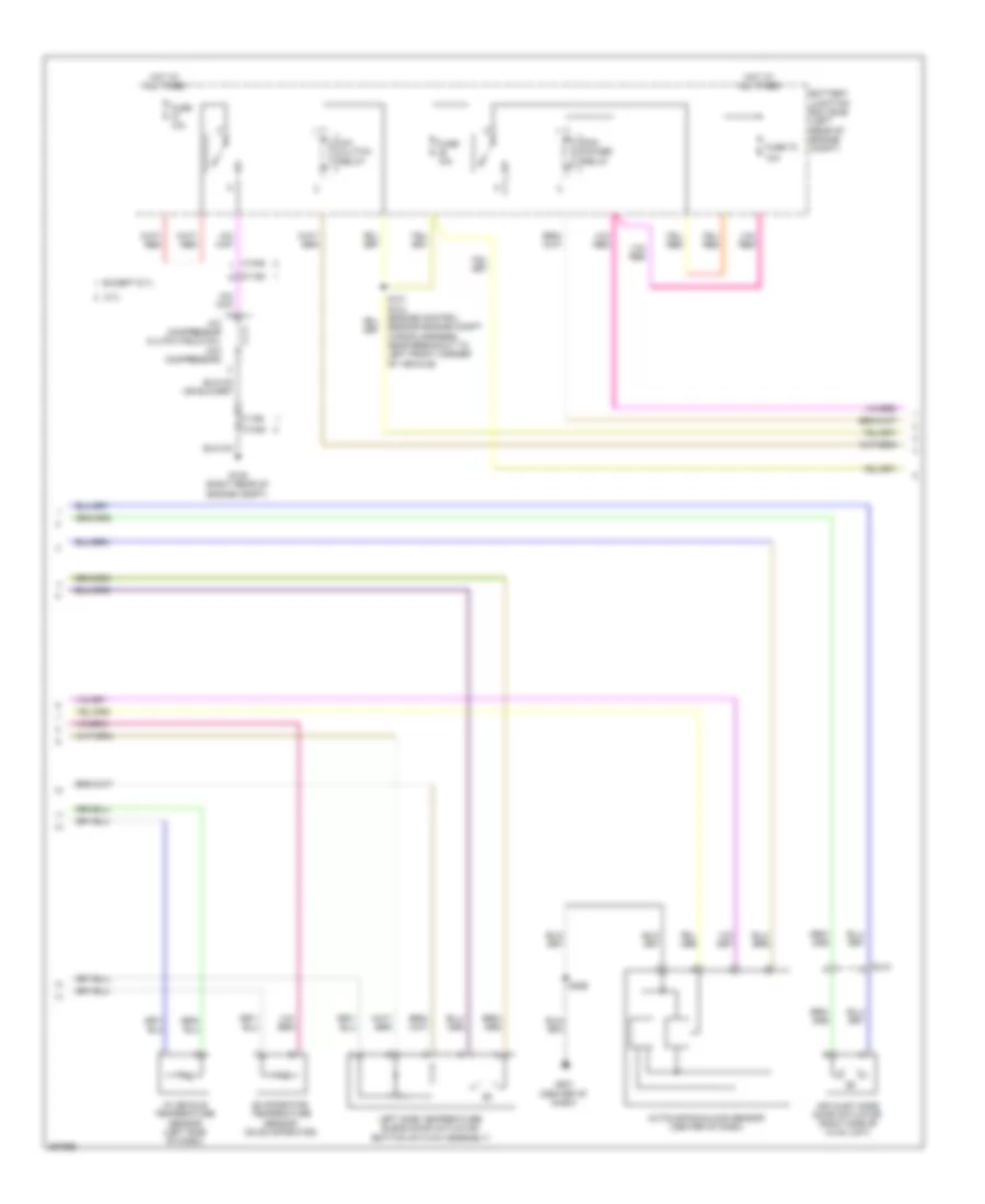
Automatic A/C Wiring Diagram (2 of 3) for Ford F550 Super Duty 2012
List of elements for Automatic A/C Wiring Diagram (2 of 3) for Ford F550 Super Duty 2012:
- 10a
- 6.7l
- A/c clutch relay
- A/c compressor clutch field coil (a/c compressor)
- Air inlet mode door actuator (right side of hvac unit)
- Autolamp/sunload sensor (center of dash)
- Battery junction box (bjb) (left rear of engine compt)
- C1046
- C1168
- C213
- Evaporator temperature sensor (on evaporator)
- Except 6.7l
- Fuse 10a
- Fuse 72
- G108 (right rear of engine compt)
- G201 (center of dash)
- Hot at all times
- In vehicle temperature sensor (left side of dash)
- Left side temperature blend door actuator (bottom of hvac assembly)
- Pcm power relay
- S226
- Sensor engine compt wiring harness, near breakout to left front corner of vehicle)
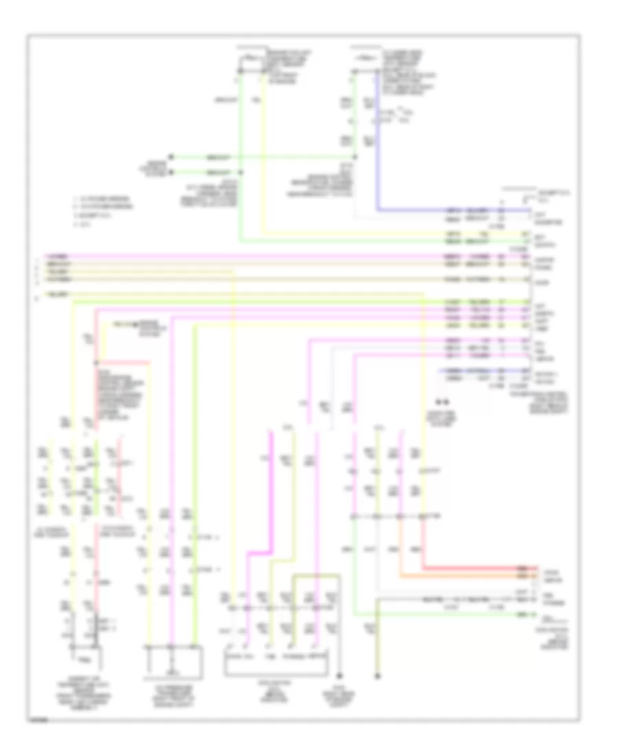
Automatic A/C Wiring Diagram (3 of 3) for Ford F550 Super Duty 2012
List of elements for Automatic A/C Wiring Diagram (3 of 3) for Ford F550 Super Duty 2012:
- 6.2l
- 6.7l
- 6.8l
- A/c pressure transducer (right front of engine compt)
- Aat
- Accr
- Acpt
- Ambient air temperature (aat) sensor (front passenger's rear view mirror assembly)
- C1046
- C1047
- C1148
- C1163
- C1165
- C1220
- C1232b
- C1232e
- C133
- C175b
- C175e
- C211
- C212
- C263
- C265
- C601
- C651
- C655
- Ce237
- Ch302
- Cht
- Computer data lines system
- Cooling fan (6.2l) (behind radiator)
- Cooling fan (6.7l) (behind radiator)
- Cylinder head temperature (cht) sensor (except 6.7l) (6.2l: rear of block, under intake) (6.8l: rear of right cylinder head)
- E-sigrtne
- Ect
- Engine controls system
- Engine coolant temperature (ect) sensor (6.7l) (top front of engine)
- Except 6.7l
- Fcv
- Fss
- G103 (right rear of engine compt)
- Hs can +
- Hs can -
- Kapwr
- Le111
- Le424
- Nca
- Pcmrc
- Powertrain control module (pcm) (right rear of engine compt)
- Pwrgnd
- Re405
- Re407
- Red
- S1013 (6.7l diesel engine harness, near breakout to intake throttle actuator)
- S116 (6.2l) (engine control sensor & fuel charge wiring harness, near breakout to c133)
- Sbb72
- Sig rtn
- Sigrtn
- Vbpwr
- Vdb04
- Vdb05
- Ve203
- Ve712
- Ve716
- Vec10
- Vh407
- Vh433
- Vpwr
- Vref
- W/ power mirrors
- W/ window one touchup
- W/o power mirrors
- W/o window one touchup
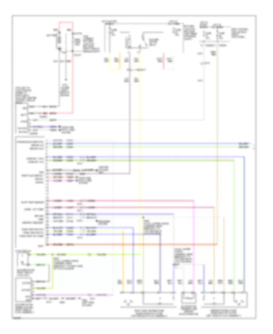
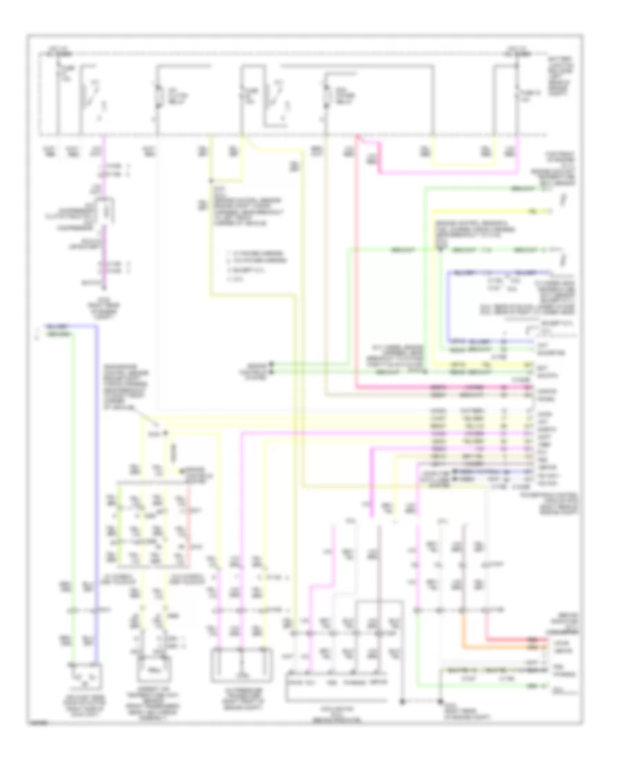
Manual A/C Wiring Diagram (1 of 2) for Ford F550 Super Duty 2012
List of elements for Manual A/C Wiring Diagram (1 of 2) for Ford F550 Super Duty 2012:
- (center of dash) g201
- (hvac jumper wiring harness, near breakout to top center of hvac housing) s251
- (top left of hvac module) (diesel w/ rapid heat) auxiliary heater control module (ahcm)
- Batt
- Battery
- Battery junction box (bjb) (left rear of engine compt)
- Blower motor (right end of hvac unit)
- Blower motor relay
- Blower motor speed control (right side of hvac assembly)
- Body control module (bcm) (right kick panel)
- C1617e
- C1617f
- C211
- C213
- C214
- C2280a
- C2280b
- C2463a
- C2463b
- Cbp37
- Ch122
- Ch123
- Ch202
- Ch203
- Ch207
- Ch208
- Ch238
- Ch239
- Computer data lines system
- Defogger system
- Defrost request
- Defrost/panel/floor mode door actuator (left side of hvac assembly)
- Evap temp sensor
- Evaporator temperature sensor (on evaporator)
- Front blower rly
- Fuse 10a
- Fuse 40a
- G101 (lower right rear of engine)
- G203 (left side of dash)
- Gd108
- Gd184
- Gnd
- High current battery junction box (bjb) (right side of engine compt)
- Hot at all times
- Hot in start or run
- Hs can+
- Hs can-
- Hvac module
- Lh111
- Mega fuse 125a
- Mode 1 act fdbk
- Mode dr 1 ccw
- Mode dr 1 cw
- Motor+
- Motor-
- Mscan+
- Mscan-
- Nca
- Pass temp act fdbk
- Pass temp dr ccw
- Pass temp dr cw
- Pwm
- Recirc ccw
- Recirc cw
- Red
- Return
- Rh111
- Right side temperature blend door actuator (top middle of hvac assembly)
- S226
- S250 (hvac jumper wiring harness, near breakout to top center of hvac housing)
- S257 (hvac jumper wiring harness, near breakout to right side of hvac housing)
- S286
- Sbp46
- Sdf05
- Variable blower ctrl
- Vbat
- Vdb04
- Vdb05
- Vdb06
- Vdb07
- Vh101
- Vh406
- Vh437
- Vh440
- Vpwr
- Vref
Manual A/C Wiring Diagram (2 of 2) for Ford F550 Super Duty 2012
List of elements for Manual A/C Wiring Diagram (2 of 2) for Ford F550 Super Duty 2012:
- (6.7l diesel engine harness, near breakout to intake throttle actuator) s1013
- (behind radiator) (6.7l) cooling fan
- (engine control sensor & fuel charge wiring harness, near breakout to c133) (6.2l) s116
- (s239 engine control sensor engine compt wiring harness, near breakout to right front corner of vehicle)
- (top front of engine) (6.7l) engine coolant temperature (ect) sensor
- 10a
- 6.2l
- 6.7l
- 6.8l
- A/c clutch relay
- A/c compressor clutch field coil (a/c compressor)
- A/c pressure transducer (right front of engine compt)
- Aat
- Accr
- Acpt
- Air inlet mode door actuator (right side of hvac unit)
- Ambient air temperature (aat) sensor (front passenger's rear view mirror assembly)
- Battery junction box (bjb) (left rear of engine compt)
- C1046
- C1047
- C1148
- C1163
- C1165
- C1168
- C1220
- C1232b
- C1232e
- C133
- C175b
- C175e
- C211
- C212
- C213
- C263
- C265
- C601
- C651
- C655
- Ce237
- Ch302
- Cht
- Computer data lines system
- Cooling fan (6.2l) (behind radiator)
- Cylinder head temperature (cht) sensor (except 6.7l) (6.2l: rear of block, under intake) (6.8l: rear of right cylinder head)
- E-sigrtne
- Ect
- Engine compt wiring harness, near breakout to left front corner of vehicle)
- Engine controls system
- Except 6.7l
- Fcv
- Fss
- Fuse 10a
- Fuse 72
- G103 (right rear of engine compt)
- G108 (right rear of engine compt)
- Hot at all times
- Hs can +
- Hs can -
- Kapwr
- Le111
- Le424
- Nca
- Pcm power relay
- Pcmrc
- Powertrain control module (pcm) (right rear of engine compt)
- Pwrgnd
- Re405
- Re407
- Red
- S100
- Sbb72
- Sig rtn
- Sigrtn
- Vbpwr
- Vdb04
- Vdb05
- Ve203
- Ve712
- Ve716
- Vec10
- Vh407
- Vh433
- Vpwr
- Vref
- W/ power mirrors
- W/ window one touchup
- W/o power mirrors
- W/o window one touchup