AIR CONDITIONING
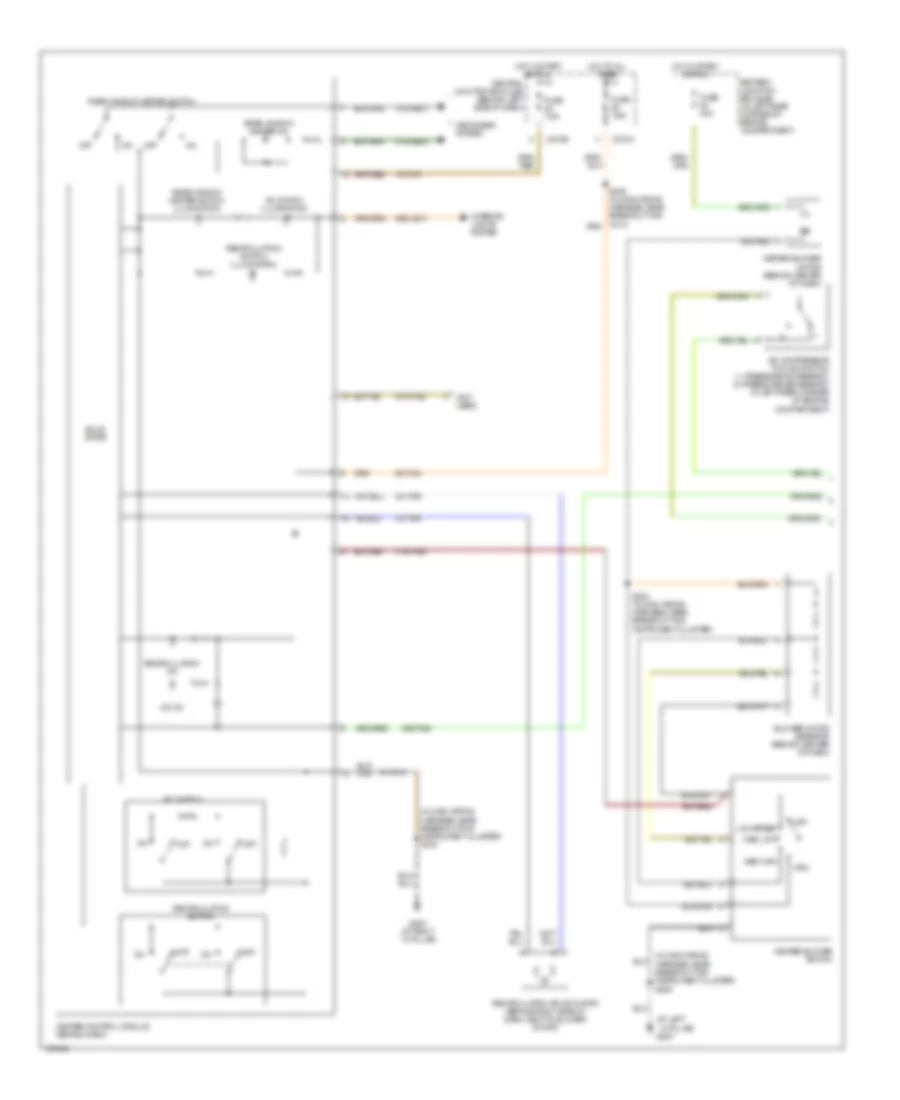
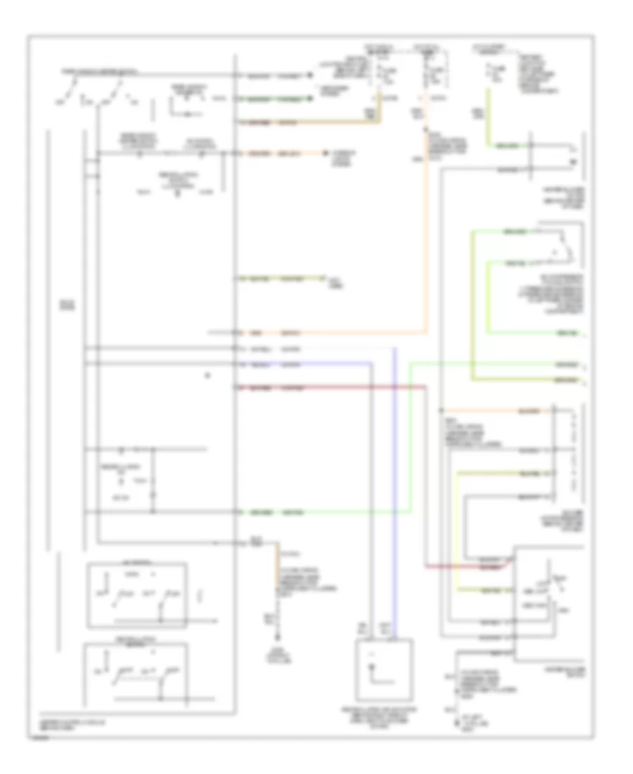
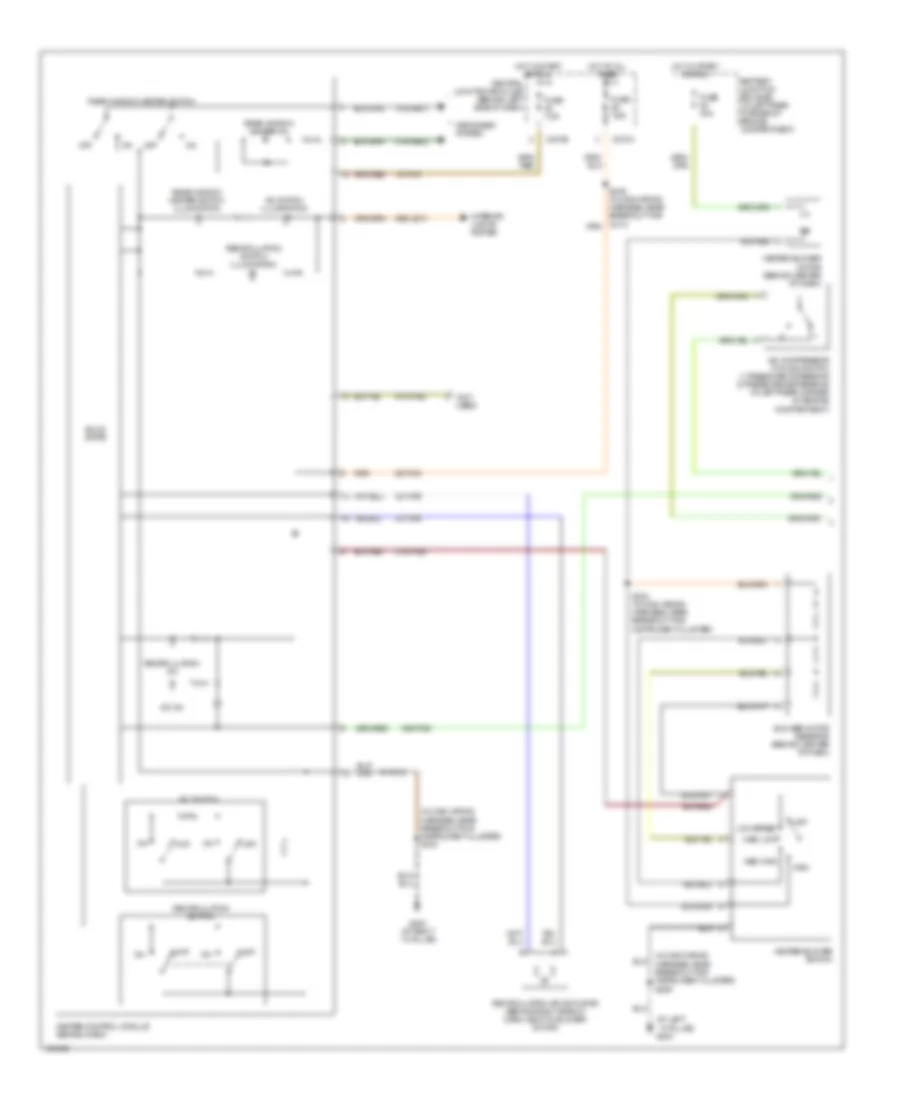
Heater Wiring Diagram for Ford Focus LX 2004

List of elements for Heater Wiring Diagram for Ford Focus LX 2004:
- (at left ``a" pillar) g204
- (at right ``a" pillar) g203
- (in main wiring
- (in main wiring harness, near breakout for instrument cluster) s224
- (not used)
- 15-fa13
- 29-fa13
- 29s-le10
- 31s-fa26
- 31s-hb22
- 31s-hb31
- 32-fa76
- 33-fa76
- 91-fa13
- 91s-fa20
- Battery junction box (bjb) (in left rear corner of engine compartment)
- Blower motor resistor (behind center of dash)
- C270a
- C270e
- Central junction box (cjb) (behind left side of dash)
- Defogger system
- Fuse 40a
- Fuse 7.5a
- Harness, near breakout for instrument cluster) s212
- Heater blower motor (behind center of dash)
- Heater blower switch
- Heater control module (behind dash)
- High
- Hot at all times
- Hot in start or run
- Interior lights system
- Low speed
- Medium high
- Medium low
- Off
- Rear window heater on
- Rear window heater switch
- Rear window heater switch illumination
- Recirculation air actuator (behind right side of dash, next to blower motor)
- Recirculation on
- Recirculation switch
- Recirculation switch illumination
- S249 (in main wiring harness, near breakout for c213)
- Solid state
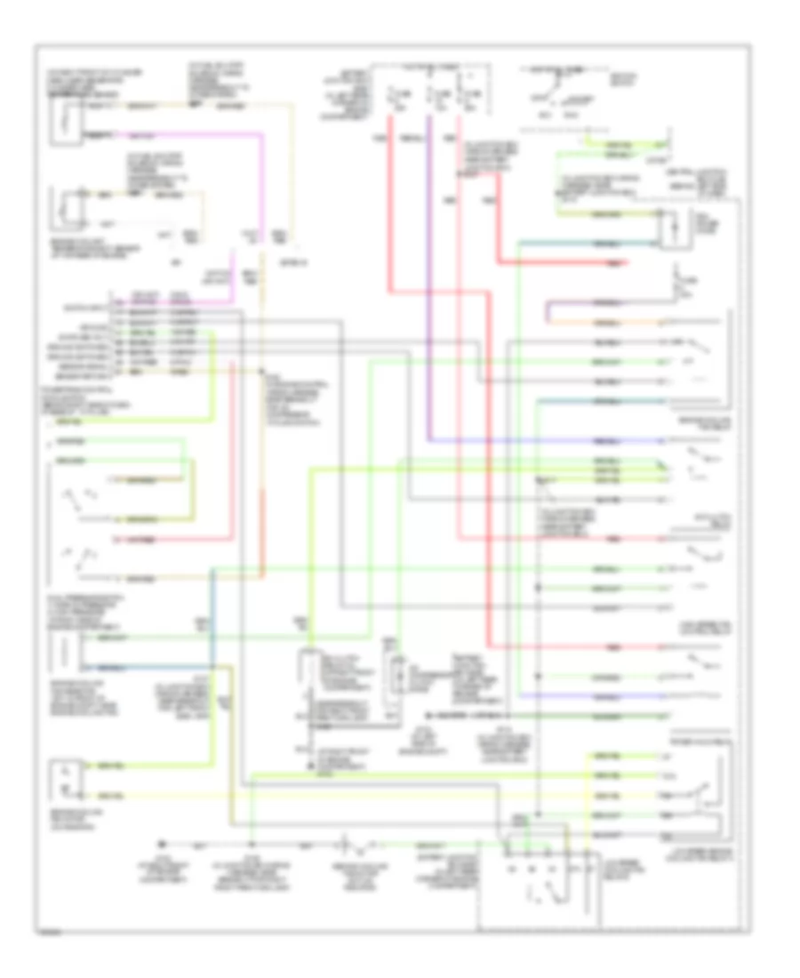
2.0L
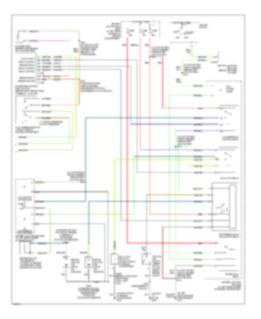
2.0L, Manual A/C Wiring Diagram, Except SVT (1 of 2) for Ford Focus LX 2004
List of elements for 2.0L, Manual A/C Wiring Diagram, Except SVT (1 of 2) for Ford Focus LX 2004:
- (at left ``a" pillar) g204
- (in main wiring
- (in main wiring harness, near breakout for instrument cluster) s212
- (not used)
- 15-fa13
- 15s-fa38
- 29-fa13
- 29s-le10
- 31s-fa26
- 31s-hb22
- 31s-hb31
- 32-fa76
- 33-fa76
- 91-fa13
- 91s-fa20
- A/c compressor cycling switch (1: pressure increasing) (2: pressure decreasing) (in left rear corner of engine compartment)
- A/c on
- A/c switch
- A/c switch illumination
- Battery junction box (bjb) (in left rear corner of engine compartment)
- Blower motor resistor (behind center of dash)
- C270a
- C270e
- Central junction box (cjb) (behind left side of dash)
- Defogger system
- Fuse 40a
- Fuse 7.5a
- G203 (at right ``a" pillar)
- Harness, near breakout for instrument cluster) s206
- Heater blower motor (behind center of dash)
- Heater blower switch
- Heater control module (behind dash)
- High
- Hot at all times
- Hot in start or run
- Interior lights system
- Low speed
- Med high
- Med low
- Off
- Rear window heater on
- Rear window heater switch
- Rear window heater switch illumination
- Recirculation air actuator (behind right side of dash, next to blower motor)
- Recirculation on
- Recirculation switch
- Recirculation switch illumination
- S224 (in main wiring harness, near breakout for instrument cluster)
- Solid state
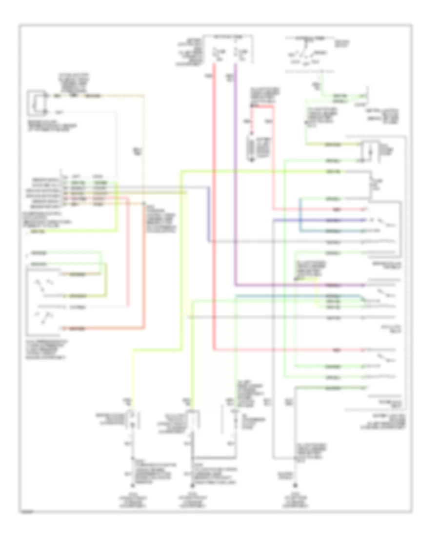
2.0L, Manual A/C Wiring Diagram, Except SVT (2 of 2) for Ford Focus LX 2004
List of elements for 2.0L, Manual A/C Wiring Diagram, Except SVT (2 of 2) for Ford Focus LX 2004:
- (at right front of engine compartment) g102
- (in fuel shutoff solenoid wiring harness, near breakout to intake system) s198
- (in junction box wiring harness,
- (in junction box wiring harness, near battery junction box) s119
- (in junction box wiring harness, near battery junction box)
- (near breakout for right front park/turn lamp)
- (on right front of cylinder head, near generator) cylinder head temperature sensor
- 15s-re8
- 31s-fa11
- 31s-pa17
- 31s-pa21
- 31s-pa7
- 8-pa13
- 8-rj5 8-rj33
- 87a
- 9-re8
- A/c clutch field coil (at right front of engine compartment)
- A/c clutch relay
- A/c compressor clutch diode
- Acc
- Battery junction box (bjb) (in left rear corner of engine compartment)
- C270e
- Central junction box (cjb) (behind left side of dash)
- Cycling switch)
- Dual pressure switch 1) normal pressure 2) high pressure (at right side of engine compartment)
- Engine coolant temperature (ect) sensor (at top rear of engine)
- Engine cooling fan motor (on radiator)
- Engine cooling fan relay
- Engine cooling fan resistor (svt: in front of engine compt, near engine cooling fan)
- Fuse 10a
- Fuse 20a
- Fuse 30a
- Fuse 50a
- G102 (at right front of engine compartment)
- G103 (at left side of engine compt)
- Ground
- Ground switched
- High speed fan control relay
- Hot at all times
- Ignition switch
- Low speed cooling fan relay b
- Low speed engine cooling fan relay a
- Nca
- Near battery junction box) s107
- Off
- Pcm power diode
- Power hold relay
- Powertrain control module (pcm) (behind right side of dash, at base of ``a" pillar)
- Red
- Run
- S109
- S109 (in junction box wiring harness, near breakout for right front park/turn lamp)
- S117
- S118 (in junction box wiring harness, near battery junction box)
- S137 (in junction box wiring harness, near breakout for left front side lamp)
- S163 (in engine control wiring harness, near breakout for a/c compressor
- Second cooling fan motor (svt: on radiator)
- Sensor return
- Sensor signal
- Spi
- Start
- Switch input
- Switched volt
- Zetec-e
2.0L, Manual A/C Wiring Diagram, SVT (1 of 2) for Ford Focus LX 2004
List of elements for 2.0L, Manual A/C Wiring Diagram, SVT (1 of 2) for Ford Focus LX 2004:
- (at left ``a" pillar) g204
- (in main wiring
- (not used)
- 15-fa13
- 15s-fa38
- 29-fa13
- 29s-le10
- 31s-fa26
- 31s-hb22
- 31s-hb31
- 32-fa76
- 33-fa76
- 91-fa13
- 91s-fa20
- A/c compressor cycling switch 1) pressure increasing 2) pressure decreasing (in left rear corner of engine compartment)
- A/c on
- A/c switch
- A/c switch illumination
- Battery junction box (bjb) (in left rear corner of engine compartment)
- Blower motor resistor (behind center of dash)
- C270a
- C270e
- Central junction box (cjb) (behind left side of dash)
- Defogger system
- Fuse 40a
- Fuse 7.5a
- G203 (at right ``a" pillar)
- Harness, near breakout for instrument cluster) s206
- Harness, near breakout for instrument cluster) s212
- Harness, near breakout for instrument cluster)
- Heater blower motor (behind center of dash)
- Heater blower switch
- Heater control module (behind dash)
- High
- Hot at all times
- Hot in run or start
- Hot in start or run
- Interior lights system
- Low
- Med high
- Med low
- Off
- Rear window heater on
- Rear window heater switch
- Rear window heater switch illumination
- Recirculation air actuator (behind right side of dash, next to blower motor)
- Recirculation on
- Recirculation switch
- Recirculation switch illumination
- S224 (in main wiring
- Solid state
2.0L, Manual A/C Wiring Diagram, SVT (2 of 2) for Ford Focus LX 2004
List of elements for 2.0L, Manual A/C Wiring Diagram, SVT (2 of 2) for Ford Focus LX 2004:
- (in fuel shutoff solenoid wiring harness, near breakout to intake system) s198
- (in junction box wiring harness near battery junction box) s102
- (in junction box wiring harness near battery junction box) s117
- (in junction box wiring harness near battery junction box) s119
- (in junction box wiring harness, near battery junction box) s118
- (in junction box wiring
- (in left rear corner of engine compartment) battery junction box (bjb)
- 15s-re8
- 31s-fa11
- 31s-pa7
- 8-pa13
- 8-rj5
- 9-re8
- A/c clutch field coil (at right front of engine compartment)
- A/c clutch relay
- A/c compressor clutch diode
- Acc
- Battery (in left side of engine compt)
- Battery junction box (bjb) (in left rear corner of engine compartment)
- Breakout for right
- C270e
- Central junction box (cjb) (behind left side of dash)
- Dual pressure switch 1) normal pressure 2) high pressure (at right side of engine compartment)
- Engine coolant temperature (ect) sensor (at top rear of engine)
- Engine cooling fan resistor)
- Engine cooling fan motor (on radiator)
- Engine cooling fan relay
- Front park/turn lamp)
- Fuse 10a
- Fuse 20a
- Fuse 30a
- G102 (at right front of engine compartment)
- G103 (at left side of engine compartment)
- Ground switched
- Hot at all times
- Ignition switch
- Lock
- Pcm power diode
- Power hold relay
- Powertrain control module (pcm) (behind right side of dash, at base of "a" pillar)
- Red
- Run off
- S1001 (in engine cooling fan
- S109
- S163 (in engine control wiring harness, near breakout for a/c compressor cycling switch)
- Sensor return
- Sensor signal
- Start
- Switched volt
2.3L
2.3L, Manual A/C Wiring Diagram (1 of 2) for Ford Focus LX 2004
List of elements for 2.3L, Manual A/C Wiring Diagram (1 of 2) for Ford Focus LX 2004:
- (at left ``a" pillar) g204
- (in main wiring
- (in main wiring harness, near breakout for instrument cluster) s212
- (not used)
- 15-fa13
- 15s-fa38
- 29-fa13
- 29s-le10
- 31s-fa26
- 31s-hb22
- 31s-hb31
- 32-fa76
- 33-fa76
- 91-fa13
- 91s-fa20
- A/c compressor cycling switch 1) pressure increasing 2) pressure decreasing (in left rear corner of engine compartment)
- A/c on
- A/c switch
- A/c switch illumination
- Battery junction box (bjb) (in left rear corner of engine compartment)
- Blower motor resistor (behind center of dash)
- C270a
- C270e
- Central junction box (cjb) (behind left side of dash)
- Defogger system
- Fuse 40a
- Fuse 7.5a
- G203 (at right ``a" pillar)
- Harness, near breakout for instrument cluster) s206
- Heater blower motor (behind center of dash)
- Heater blower switch
- Heater control module (behind dash)
- High
- Hot at all times
- Hot in start or run
- Interior lights system
- Low speed
- Med high
- Med low
- Off
- Rear window heater on
- Rear window heater switch
- Rear window heater switch illumination
- Recirculation air actuator (behind right side of dash, next to blower motor)
- Recirculation on
- Recirculation switch
- Recirculation switch illumination
- S224 (in main wiring harness, near breakout for instrument cluster)
- Solid state
2.3L, Manual A/C Wiring Diagram (2 of 2) for Ford Focus LX 2004
List of elements for 2.3L, Manual A/C Wiring Diagram (2 of 2) for Ford Focus LX 2004:
- (1: normal pressure) (2: high pressure)
- (at left
- (at right front of engine compartment) g102
- (at right ``a" pillar) g202
- (in engine cooling fan wiring harness, at breakout for engine cooling fan resistor) s1002
- (in junction box wiring harness, near battery junction box) s107
- (in junction box wiring harness, near battery junction box) s108
- (in junction box wiring harness, near battery junction box) s117
- (in junction box wiring harness, near battery junction box) s118
- (in junction box wiring harness, near battery junction box) s119
- (near breakout for right front park/ turn lamp) s109
- 15s-re8
- 31s-fa11
- 31s-pa17
- 31s-pa7
- 8-pa13
- 8-rj33
- 9-rj33
- A/c clutch field coil (at right front of engine compartment)
- A/c clutch relay
- A/c compressor clutch diode
- Acc
- Battery junction box (bjb) (in left rear corner of engine compartment)
- Battery junction box (bjb) (in left rear corner of engine compt)
- C175b
- C175e
- C270e
- Central junction box (cjb) (behind left side of dash)
- Compressor cycling switch)
- Cooling fan motor diode
- Cooling fan run-on thermo switch (at left side of engine compt)
- Cylinder head temperature sensor (on cylinder head)
- Dual pressure switch (at right side of engine compartment)
- Engine cooling fan motor (on radiator)
- Engine cooling fan resistor (in front of engine compartment, near engine cooling fan)
- Fuse 10a
- Fuse 20a
- Fuse 30a
- Fuse 50a
- High speed run-on cooling fan relay
- Hot at all times
- Ignition switch
- Low speed fan control relay
- Off
- Pcm power diode
- Power hold relay
- Powertrain control module (pcm) (behind right side of dash, at base of ``a" pillar)
- Red
- Relay control
- Run
- S1001 (in engine cooling fan wiring harness near breakout for engine cooling fan resistor)
- S162 (in engine control wiring harness, near breakout for a/c
- S198 (in fuel shut-off solenoid wiring harness, near breakout to intake system)
- S279 (near breakout for c211)
- Second cooling fan motor (on radiator)
- Sensor return
- Sensor signal
- Side of engine compartment) g103
- Start
- Switch input