AIR CONDITIONING
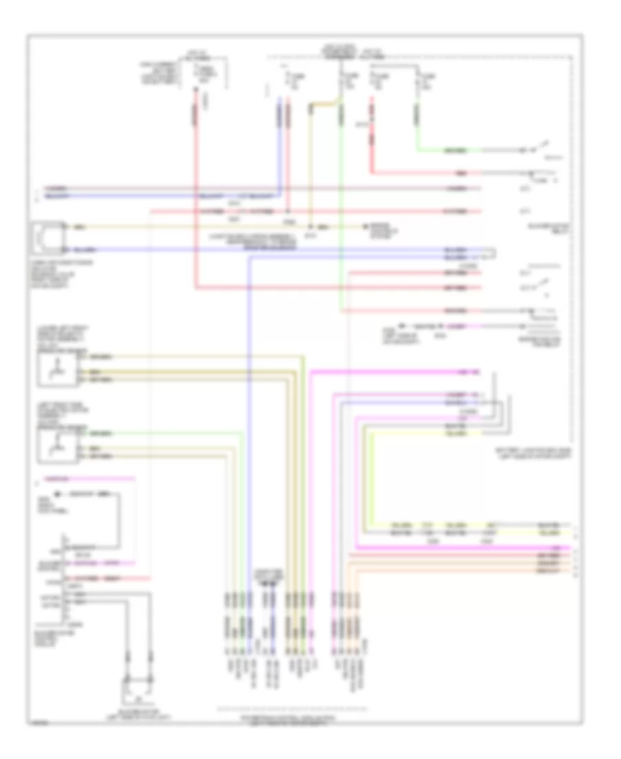
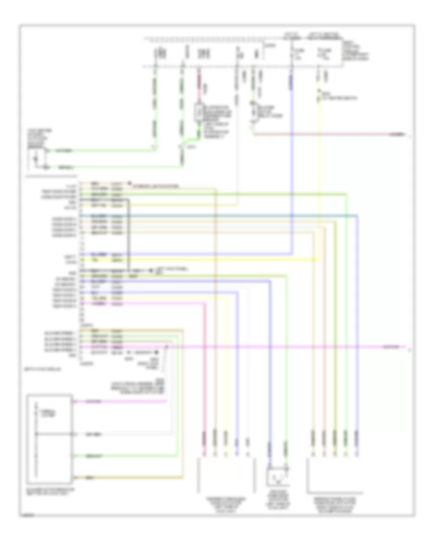
Automatic A/C Wiring Diagram, Electric (1 of 3) for Ford Focus ST 2014

List of elements for Automatic A/C Wiring Diagram, Electric (1 of 3) for Ford Focus ST 2014:
- (left center of dash) in-vehicle temperature/ humidity sensor
- (left kick panel) g201
- (top center of dash) autolamp/ sunload sensor
- Air inlet blend door actuator (upper left side of hvac unit)
- Aspirator gnd
- Auto lamps sens
- Blower control
- Bmrc
- Body control module (lower right side of dash)
- C213
- C2280a
- C2280c
- C2280f
- C228a
- C228b
- Ch123
- Ch201
- Ch202
- Ch203
- Ch204
- Ch205
- Ch206
- Ch207
- Ch208
- Ch209
- Ch210
- Ch211
- Ch212
- Ch213
- Ch214
- Ch215
- Ch227
- Ch228
- Ch229
- Ch230
- Ch231
- Ch237
- Ch238
- Ch239
- Ch240
- Ch241
- Computer data lines system
- Defr a
- Defr b
- Defr c
- Defr d
- Defr pwr
- Defrost mode door actuator (right side of hvac unit)
- Disc floor l sens
- Disc floor r sens
- Disc panel l sens
- Disc panel r sens
- Evap temp sens
- Evaporator temperature sensor (left side of hvac evaporator assembly)
- Fuse 10a
- Gd133
- Gnd
- Hot at all times
- Hs can+
- Hs can-
- Humidity gnd
- Hvac control module
- In-car sens
- L sunl sens
- L temp a
- L temp b
- L temp c
- L temp d
- L temp power
- Left center register air discharge temperature sensor (left center register side of top center dash)
- Left footwell air discharge temperature sensor (left footwell side of hvac unit)
- Left temperature blend door actuator (lower left side of hvac unit)
- Micro
- Ms can+
- Ms can-
- Pa/fl a
- Pa/fl b
- Pa/fl c
- Pa/fl d
- Pa/fl pwr
- Panel/floor mode door actuator (lower left side of hvac unit)
- R sunl sens
- R temp a
- R temp b
- R temp c
- R temp d
- R temp power
- Recirc a
- Recirc b
- Recirc c
- Recirc d
- Recirc power
- Rh103
- Rh104
- Rh105
- Rh107
- Right center register air discharge temperature sensor (right center register side of top center dash)
- Right footwell air discharge temperature sensor (right footwell side of hvac unit)
- Right temperature blend door actuator (left side of hvac unit)
- S202
- S246 (main wiring assembly, near breakout to front controls interface module)
- Sbp27
- Sens
- Sens gnd
- Sigrtn
- Vbatt
- Vdb04
- Vdb05
- Vdb06
- Vdb07
- Vh101
- Vh406
- Vh409
- Vh410
- Vh411
- Vh412
- Vh413
- Vh414
- Vh416
- Vh417
- Vln52
- Vpwr
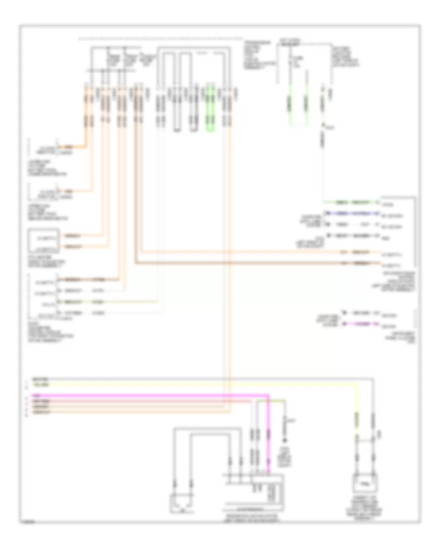
Automatic A/C Wiring Diagram, Electric (2 of 3) for Ford Focus ST 2014
List of elements for Automatic A/C Wiring Diagram, Electric (2 of 3) for Ford Focus ST 2014:
- (junction box wiring assembly, near breakout to brake booster solenoid)
- (left front side of electric motor assembly) a/c high pressure sensor
- (lower left front side of eclectic motor assembly) a/c low pressure sensor
- A10
- Aat
- Ac sol lsd
- Achp
- Aclp
- Battery junction box (bjb) (left side of motor compt)
- Blower control
- Blower motor (left side of hvac unit)
- Blower motor control module
- Blower motor relay
- C1035c
- C1617j
- C175a
- C175b
- C214
- C221
- C238
- C297a
- C297b
- C340
- Cabin air conditioning isolator solenoid valve (right side of motor compt)
- Cbb47
- Cet25
- Computer data lines system
- Engine controls system
- Engine cooling fan relay
- Ev hs can+
- Ev hs can-
- Fcv
- Fuse 10a
- Fuse 40a
- Fuse 5a
- G105 (left side of motor compt)
- G202 (right kick panel)
- Gd138
- Gnd
- High current battery junction box (on battery)
- Hot at all times
- Hot w/ pcm power relay energized
- Hvil sense
- Hvil source
- Lh108
- Mega fuse 8 50a
- Motor+
- Motor-
- Nca
- Powertrain control module (pcm) (left front of motor compt)
- Red
- Rh107
- Rh108
- S102
- S115
- S131
- S132
- S203
- Sig rtn
- Sigrtn
- Vdb04
- Vdb05
- Ve203
- Ve740
- Vh101
- Vh422
- Vpwr
- Vref
- Za113
- Za114
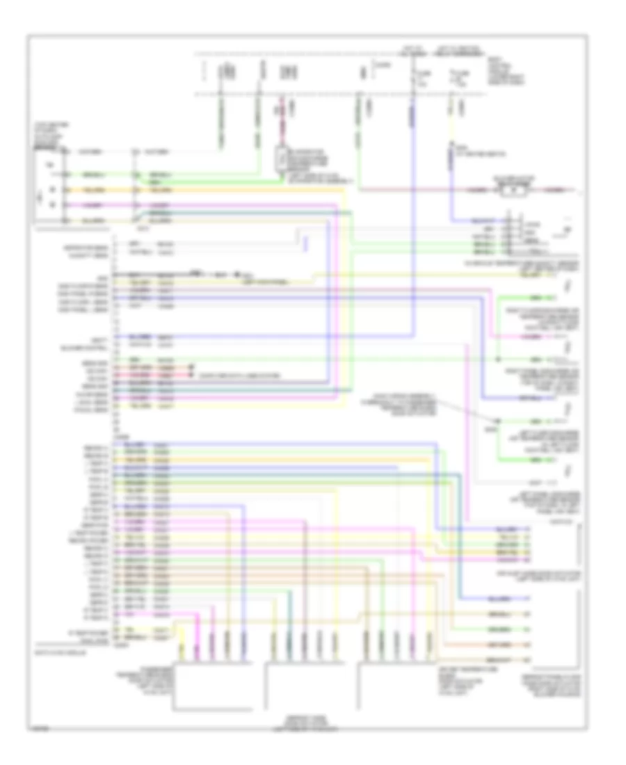
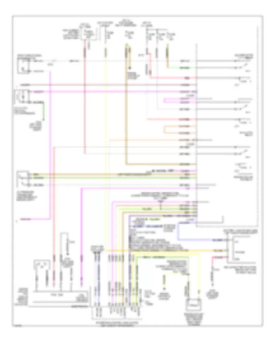
Automatic A/C Wiring Diagram, Electric (3 of 3) for Ford Focus ST 2014
List of elements for Automatic A/C Wiring Diagram, Electric (3 of 3) for Ford Focus ST 2014:
- Air conditioning control module (accm) (left side of electric motor assembly)
- Ambient air temperature (aat) sensor (in right exterior rearview mirror assembly)
- Battery junction box (bjb) (left side of motor compt)
- C1035c
- C1457a
- C1822a
- C1822b
- C1822c
- C1822d
- C1822e
- C1822f
- C1822g
- C1822h
- C4804d
- C4805a
- C626
- Cbb12
- Computer data lines system
- Cyd01
- Cyd02
- Dc/dc converter control module (top front of electric motor assembly)
- Electronics
- Engine cooling fan motor (left front of motor compt)
- Ev hs can+
- Ev hs can-
- Front fuse 20a
- Fuse 10a
- G104 (left front of motor compt)
- G105 (left side of motor compt)
- Gd130
- Gd151
- Gnd
- Hdc52
- Hdc53
- Hot in run or start
- Hv batt(+)
- Hv batt(-)
- Hv main positive
- Hv+
- Hv-
- Hvil
- Hvil in
- Hvil out
- Hyt01
- Hyt02
- Instrument panel cluster (ipc)
- Lower high voltage battery pack (under rear seats)
- Middle fuse 40a
- Ms can+
- Ms can-
- Nca
- Ptc heater (front of electric motor assembly)
- Pwr
- Rear fuse 40a
- S101
- S151
- Sbb05
- Transmission control module (tcm) (top of electric motor assembly)
- Upper high voltage battery pack (behind rear seats)
- Variable fan ctrl
- Vdb04
- Vdb05
- Ve203
- Vpwr
- Za113
- Za114
Automatic A/C Wiring Diagram, Except Electric (1 of 2) for Ford Focus ST 2014
List of elements for Automatic A/C Wiring Diagram, Except Electric (1 of 2) for Ford Focus ST 2014:
- (main wiring assembly, in breakout to passenger temperature blend door actuator)
- (top center of dash) autolamp/ sunload sensor
- Air inlet mode door actuator (left side of hvac unit)
- Aspirator sens
- Auto lamps sens
- Blower control
- Blower motor relay diode
- Bmrc
- Body control module (lower right side of dash)
- C213
- C2280a
- C2280c
- C2280f
- C228a
- C228b
- Ch123
- Ch201
- Ch202
- Ch203
- Ch204
- Ch205
- Ch206
- Ch207
- Ch208
- Ch209
- Ch210
- Ch211
- Ch212
- Ch213
- Ch214
- Ch215
- Ch227
- Ch228
- Ch229
- Ch230
- Ch231
- Ch237
- Ch238
- Ch239
- Ch240
- Ch241
- Computer data lines system
- Datc hvac module
- Defr a
- Defr b
- Defr c
- Defr d
- Defr pwr
- Defrost mode door actuator (left side of hvac unit)
- Defrost/panel/floor mode door actuator (right side of hvac blower housing)
- Disc floor l sens
- Disc floor r sens
- Disc panel l sens
- Disc panel r sens
- Driver temperature blend door actuator (left side of hvac unit)
- Evap temp sens
- Evaporator air discharge temperature sensor (left side of hvac evaporator assembly)
- Fuse 10a
- Fuse 7.5a
- G201 (left kick panel)
- Gd133
- Gnd
- Hot at all times
- Hot w/ ignition relay energized
- Humidity sens
- In-car sens
- In-vehicle temperature/humidity sensor (left center of dash)
- L sunl sens
- L temp a
- L temp b
- L temp c
- L temp d
- L temp power
- Left floor discharge air temperature sensor (in left floor footwell air vent)
- Left panel discharge air temperature sensor (top of dash, in left panel air vent)
- Micro
- Ms can+
- Ms can-
- Pa/fl a
- Pa/fl b
- Pa/fl c
- Pa/fl d
- Pa/fl pwr
- Passenger temperature blend door actuator (left side of hvac unit)
- R sunl sens
- R temp a
- R temp b
- R temp c
- R temp d
- R temp power
- Recirc a
- Recirc b
- Recirc c
- Recirc d
- Recirc power
- Rh103
- Rh104
- Rh105
- Rh107
- Right floor discharge air temperature sensor (in right floor footwell air vent)
- Right panel discharge air temperature sensor (top of dash, in right panel air vent)
- S201
- S230 (w/ heated seats)
- S246
- Sbp27
- Sens
- Sens gnd
- Sigrtn
- Vbatt
- Vdb06
- Vdb07
- Vh101
- Vh406
- Vh409
- Vh410
- Vh411
- Vh412
- Vh413
- Vh414
- Vh416
- Vh417
- Vln52
- Vpwr
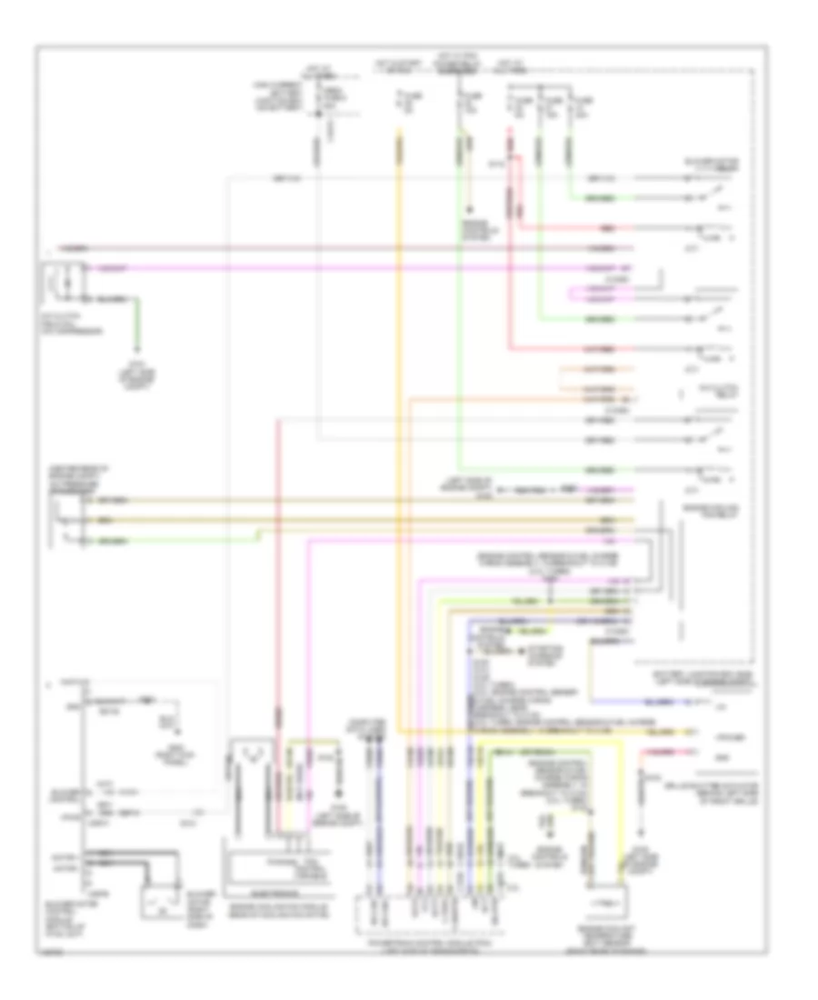
Automatic A/C Wiring Diagram, Except Electric (2 of 2) for Ford Focus ST 2014
List of elements for Automatic A/C Wiring Diagram, Except Electric (2 of 2) for Ford Focus ST 2014:
- (center rear of engine compt) a/c pressure transducer
- (engine control sensor & fuel charge wiring assembly, in breakout to c133) (2.0l turbo) s132
- (engine control sensor & fuel charge wiring assembly, in breakout to c139) (2.ol turbo) s128
- (left side of engine compt) g105
- (not used)
- (or re454)
- 2.0l
- 2.0l turbo
- A/c clutch field coil (a/c compressor)
- A/c clutch relay
- Accr
- Acpt
- Battery junction box (bjb) (left side of engine compt)
- Blower control
- Blower motor (right side of dash)
- Blower motor control module (bottom of hvac unit)
- Blower motor relay
- C-sigrtn
- C-vref
- C1035c
- C1381b
- C1381e
- C1617j
- C175b
- C175e
- C212
- C297a
- C297b
- Ch109
- Computer data lines system
- Ect
- Electronics
- Engine controls system
- Engine coolant temperature (ect) sensor (right rear of engine)
- Engine cooling fan module (rear of cooling fan motor)
- Engine cooling fan relay
- Fan control variable
- Fcv
- Fuse 10a
- Fuse 15a
- Fuse 40a
- Fuse 5a
- G104 (left side of engine compt)
- G105 (left side of engine compt)
- G202 (right kick panel)
- Gd130
- Gd138
- Gnd
- Grille shutter actuator (behind left side of front grille)
- High current battery junction box (on battery)
- Hot at all times
- Hot in start or run
- Hot w/ pcm power relay energized
- Hs can+
- Hs can-
- Le424
- Lh108
- Lin
- Mega fuse 8 50a
- Motor +
- Motor -
- Nca
- Powertrain control module (pcm) (left side of transmission)
- Pwr
- Re141
- Red
- Rh108
- S102
- S115
- S120 (2.0l) s129 (2.0l turbo) (2.0l: engine control sensor & fuel charge wiring harness, near breakout to c133) (2.0l turbo: engine control sensor & fuel charge wiring assembly, in breakout to c139) (or vdn08)
- S203
- Sbb05
- Sig rtn
- Starting/ charging system
- Vdb04
- Vdb05
- Vdc46
- Ve203
- Ve716
- Vpower
- Vpwr
Manual A/C Wiring Diagram (1 of 2) for Ford Focus ST 2014
List of elements for Manual A/C Wiring Diagram (1 of 2) for Ford Focus ST 2014:
- (left kick panel) g201
- (top center of dash) autolamp/ sunload sensor
- A/c on
- A/c on sw
- Air inlet mode door actuator (left side of hvac unit)
- Auto lamps sens
- Blower motor relay diode
- Blower motor resistor (bottom of hvac unit)
- Blower speed 1
- Blower speed 2
- Blower speed 3
- Blower speed 4
- Bmrc
- Body control module (lower right side of dash)
- C213
- C2280a
- C2280c
- C2280f
- C2357a
- C2357b
- Cbb28
- Cbp04
- Ch123
- Ch201
- Ch202
- Ch203
- Ch204
- Ch205
- Ch207
- Ch208
- Ch232
- Ch233
- Ch234
- Ch235
- Ch236
- Ch427
- Ch428
- Ch429
- Ch434
- Cln17
- Dc recirc+
- Dc recirc-
- Defrost/panel/floor mode door actuator (right side of hvac blower housing)
- Emtc hvac module
- Evap temp sens
- Evaporator discharge air temperature sensor (left side of hvac evaporator assembly)
- Fuse 10a
- Fuse 7.5a
- G202 (right kick panel)
- Gd133
- Gd138
- Gnd
- Hot at all times
- Hot w/ ignition relay energized
- Illum
- Interior lights system
- Micro
- Mode door a
- Mode door b
- Mode door c
- Mode door d
- Mode door power
- Rh107
- S202
- S203
- S230 (w/ heated seats)
- S245 (main wiring harness, near breakout to temperature blend door actuator)
- Sbp27
- Sigrtn
- Temp door a
- Temp door b
- Temp door c
- Temp door d
- Temp door power
- Temperature blend door actuator (left side of hvac unit)
- Thermal limiter
- Vbatt
- Vh406
- Vln52
- Vpwr
Manual A/C Wiring Diagram (2 of 2) for Ford Focus ST 2014
List of elements for Manual A/C Wiring Diagram (2 of 2) for Ford Focus ST 2014:
- (engine control sensor & fuel charge wiring assembly, in breakout to c133) (2.0l turbo) s132
- (engine control sensor & fuel charge wiring assembly, in breakout to c139) (2.0l turbo) s128
- (not used)
- (or re454)
- (right side of dash) blower motor
- 2.0l & 2.0l flex fuel
- 2.0l turbo
- A/c clutch field coil (a/c compressor)
- A/c clutch relay
- A/c pressure transducer (center rear of engine compt)
- Accr
- Acpt
- Battery junction box (bjb) (left side of engine compt)
- Blower motor relay
- C-sigrtn
- C-vref
- C1035c
- C1381b
- C1381e
- C1617j
- C175b
- C175e
- C212
- Ch109
- Computer data lines system
- Ect
- Electronics
- Engine controls system
- Engine coolant temperature (ect) sensor (right rear of engine)
- Engine cooling fan module (rear of cooling fan motor)
- Engine cooling fan relay
- Fan control variable
- Fcv
- Fuse 10a
- Fuse 15a
- Fuse 40a
- Fuse 5a
- G104 (left side of engine compt)
- G105 (left side of engine compt)
- Gd130
- Gnd
- Grille shutter actuator (behind left side of front grille)
- High current battery junction box (on battery)
- Hot at all times
- Hot in start or run
- Hot w/ pcm power relay energized
- Hs can+
- Hs can-
- Le424
- Lh108
- Lin
- Mega fuse 8 50a
- Nca
- Ne203
- Powertrain control module (pcm) (left side of transmission)
- Pwr
- Re141
- Red
- Rh108
- S102
- S115
- S120 (2.0l & 2.0l flex fuel) s129 (2.0l turbo) (2.0l & 2.0l flex fuel: engine control sensor & fuel charge wiring harness, near breakout to c133) (2.0l turbo: engine control sensor & fuel (or vdn08) charge wiring assembly, in breakout to c139)
- Sbb05
- Sigrtn
- Starting/ charging system
- Vdb04
- Vdb05
- Vdc46
- Ve203
- Ve716
- Vpower