AIR CONDITIONING
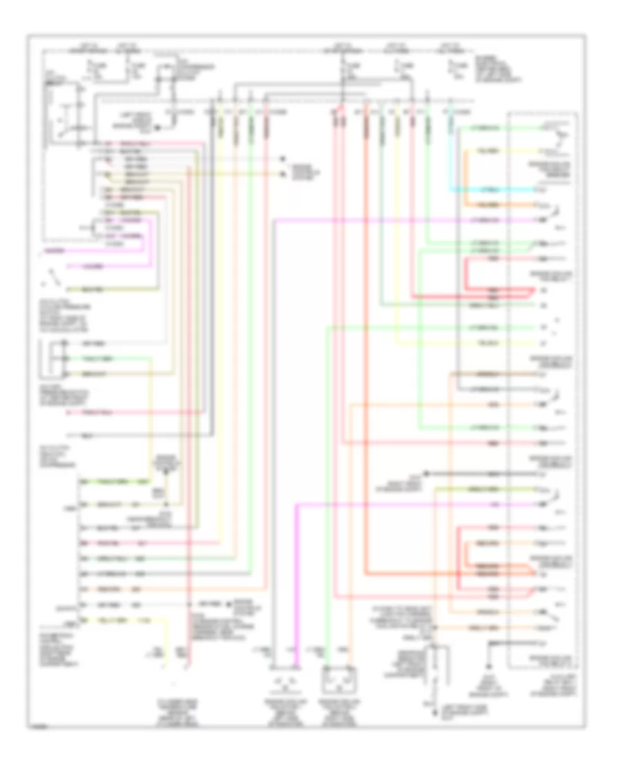
Automatic A/C Wiring Diagram (1 of 2) for Ford Freestar Limited 2004

List of elements for Automatic A/C Wiring Diagram (1 of 2) for Ford Freestar Limited 2004:
- (in heater blower motor harness, near breakout to c212) s234
- (in main harness, near breakout for g103) s202
- (right kick panel) g201
- Ambient air temperature sensor (at right front side of engine compartment)
- Autolamp/ sunload sensor (near top center of dash)
- Bussed electrical center (bec) (at left side of engine compt)
- C1035d a5
- C2280a
- C2280c
- C2280h
- C228a
- C228b
- Computer data lines system
- Control
- Driver temperature blend door actuator (behind left side of dash)
- Electronic automatic temperature control (eatc) module (center of dash)
- Fresh/recirculation door actuator (behind center of dash)
- Front blower motor (behind right side of dash)
- Front blower motor relay (left kick panel)
- Front blower motor speed controller (behind right side of dash)
- Fuse 10a
- Fuse 30a
- Fuse 5a
- G301 (left kick panel)
- Ground
- High ind status
- Hot at all times
- Hot in run
- In breakout for c214)
- In-vehicle temperature sensor (behind left side of dash)
- Low current board
- Low ind status
- Mode door actuator (behind center of dash)
- Passenger temperature blend door actuator (behind right side of dash)
- Pwr
- S201 (in main harness, in breakout for c214)
- S228 (in main harness, near breakout for c212)
- S235 (in heater blower motor harness, near breakout to passenger blend door actuator)
- Scp +
- Scp -
- Seats system
- Shift interlock system
- Sig rtn
- Signal
- Smart junction box (sjb) (behind left side of dash)
- Sw gnd
- Temp request
- Twisted pair
- Ubp
- Vbatt
- Vpwr
- Vref
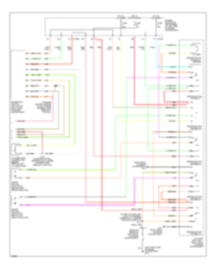
Automatic A/C Wiring Diagram (2 of 2) for Ford Freestar Limited 2004
List of elements for Automatic A/C Wiring Diagram (2 of 2) for Ford Freestar Limited 2004:
- (left front side of engine compt) g101
- 10a
- 87a
- A/c clutch cycling pressure switch (at right side of engine compt, on a/c accumulator)
- A/c clutch field coil (on a/c compressor)
- A/c clutch relay
- A/c compressor clutch diode
- A/c high pressure switch (at center front of engine compt)
- A10
- A11
- Auxiliary relay box 1 (right front of engine compt)
- Bussed electrical center (bec) (at left side of engine compt)
- C1035a
- C1035b
- C1035c
- C1035c f7
- C11 c1035b
- Cylinder head temperature sensor (rear of left cylinder head)
- D11
- Dropping resistor (left front of engine compartment)
- E11
- Engine controls system
- Engine cooling fan circuit breaker
- Engine cooling fan motor 1 (behind left side of radiator)
- Engine cooling fan motor 2 (behind right side of radiator)
- Engine cooling fan relay 1
- Engine cooling fan relay 2
- Engine cooling fan relay 3
- Engine cooling fan relay 4
- Engine cooling fan relay 5
- F11
- Fuse 10a
- Fuse 15a
- Fuse 30a
- G107 (right front of engine compt)
- Hot at all times
- Hot in start or run
- Powertrain control module (pcm) (right rear of engine compartment)
- Red
- S102 (near breakout for g103)
- S106 (in engine control sensor & fuel charge harness, near breakout for g103)
- Sig rtn
- Vref
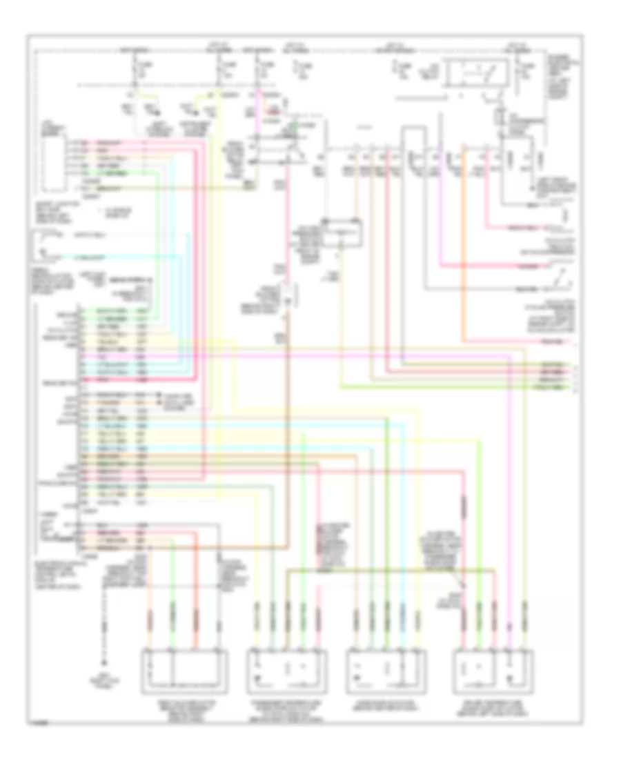
Manual A/C Wiring Diagram (1 of 2) for Ford Freestar Limited 2004
List of elements for Manual A/C Wiring Diagram (1 of 2) for Ford Freestar Limited 2004:
- (at left side of engine compt)
- (center of dash)
- (in heater blower motor harness, near breakout to passenger blend door actuator)
- (left front side of engine compartment) g101
- (left kick panel) g301
- A/c clutch
- A/c clutch cycling pressure switch (at right side of engine compt, on a/c accumulator)
- A/c clutch field coil (on a/c compressor)
- A/c clutch relay
- A/c compressor clutch diode
- A/c high pressure switch (at center front of engine compt)
- A10
- Bussed electrical center (bec)
- C1035a
- C1035b
- C1035c
- C2280a
- C2280b
- C2280c
- C2280h
- C294a
- C294b
- Computer data lines system
- D11
- Driver temperature blend door actuator (behind left side of dash)
- Electronic manual temperature control (eatc) module
- Fr blower sw
- Fresh/ recirculation door actuator (behind center of dash)
- Front blower motor (behind right side of dash)
- Front blower motor relay (left kick panel)
- Front blower motor resistor assembly (behind right side of dash)
- Fuse 10a
- Fuse 15a
- Fuse 30a
- Fuse 5a
- G201 (right kick panel)
- Ground
- High
- Hot at all times
- Hot in run
- Hot in start or run
- Illum
- Instrument cluster system
- Lock
- Low current board
- Mode door actuator (behind center of dash)
- Passenger temperature blend door actuator (w/ dual zone a/c) (behind right side of dash)
- Pnk
- Rear def ind
- Rear def sw
- S201 (in breakout for c214)
- S229 (in main harness, near breakout for right footwell courtesy lamp)
- S235 (w/ dual zone a/c)
- Scp+
- Scp-
- Shift interlock system
- Sig rtn
- Smart junction box (sjb) (behind left side of dash)
- Vpwr
- Vref
- W/ single zone a/c
Manual A/C Wiring Diagram (2 of 2) for Ford Freestar Limited 2004
List of elements for Manual A/C Wiring Diagram (2 of 2) for Ford Freestar Limited 2004:
- (in dash to headlight junction harness, in breakout to engine cooling fan relay 4) s113
- (in engine control sensor & fuel charge harness, near breakout for g103)
- (left front side of engine compartment) g101
- (right front of engine compartment) g107
- 10a
- 87a
- A11
- Auxiliary relay box 1 (right front of engine compartment)
- Bussed electrical center (bec) (at left side of engine compartment)
- C1035b c11
- Cylinder head temperature sensor (rear of left cylinder head)
- Dropping resistor (left front of engine compartment)
- E11
- Engine cooling fan circuit breaker
- Engine cooling fan motor 1 (behind left side of radiator)
- Engine cooling fan motor 2 (behind right side of radiator)
- Engine cooling fan relay 1
- Engine cooling fan relay 2
- Engine cooling fan relay 3
- Engine cooling fan relay 4
- Engine cooling fan relay 5
- F11
- F7 c1035c
- Fuse 15a
- Fuse 30a
- G107 (right front of engine compartment)
- Hot at all times
- Hot in start or run
- Powertrain control module (pcm) (right rear of engine compartment)
- Red
- S102
- S106 (in engine control sensor & fuel charge harness, near breakout for g103)
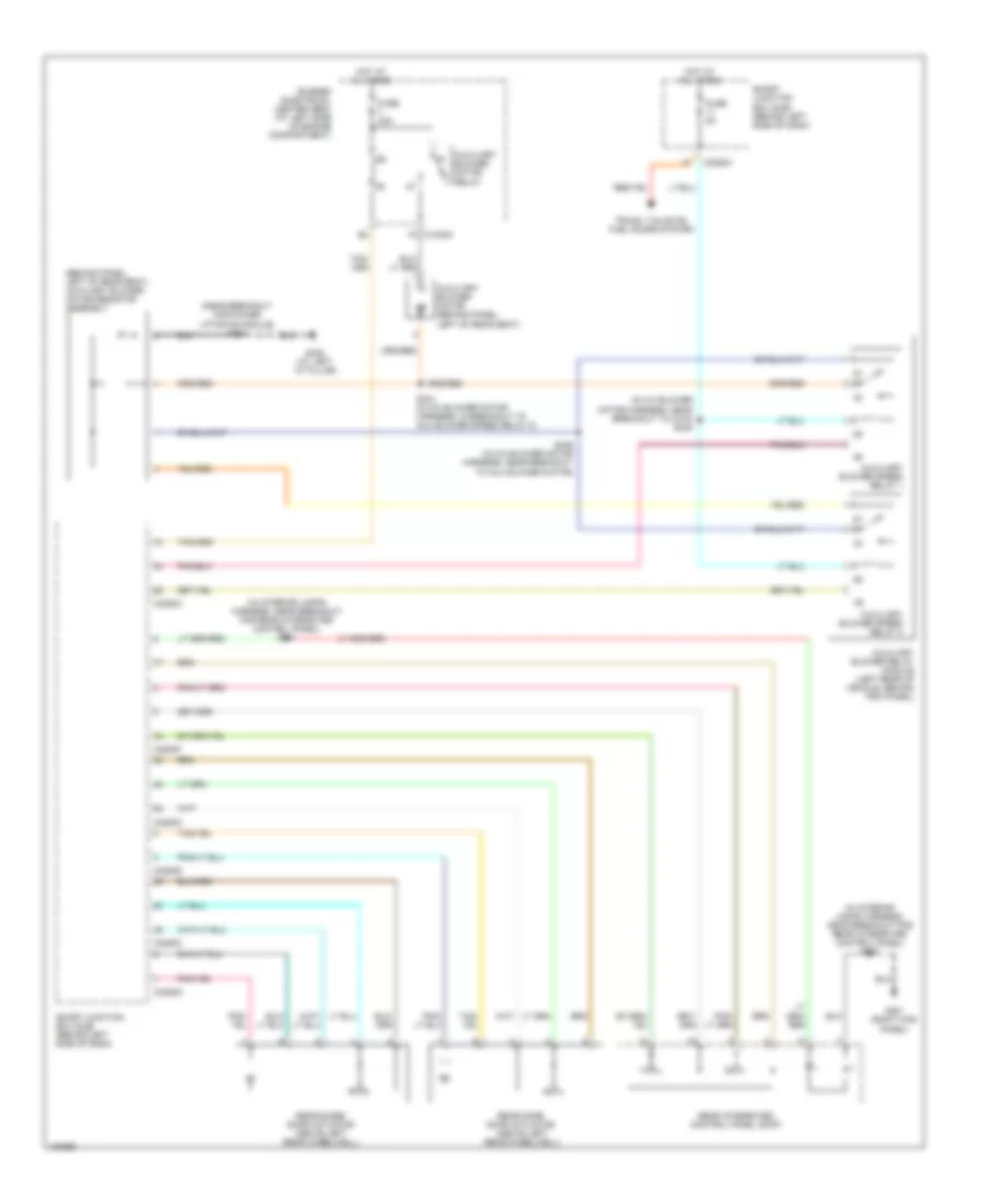
Rear A/C Wiring Diagram for Ford Freestar Limited 2004
List of elements for Rear A/C Wiring Diagram for Ford Freestar Limited 2004:
- (behind panel, left of rear seat) auxiliary blower motor resistor assembly
- (in a/c blower motor harness, near breakout to c315) s345
- (in interior lamps harness, near breakout for rear integrated control panel) s901
- (in interior lamps harness, near breakout for rear integrated control panel) s902
- (near breakout for power liftgate module) s310
- Auxiliary blower motor (behind panel, left of rear seat)
- Auxiliary blower motor relay
- Auxiliary blower relay module (left rear of vehicle, behind trim panel)
- Auxiliary blower speed relay 1
- Auxiliary blower speed relay 2
- Bussed electrical center (bec) (at left side of engine compartment)
- C2280c
- C2280d
- C2280f
- C2280h
- F4 c1035a
- Fuse 30a
- Fuse 5a
- G201 (right kick panel)
- G400 (at left ``d" pillar)
- Hot at all times
- Rear blend door actuator (above left rear wheelwell)
- Rear integrated control panel (ricp)
- Rear mode door actuator (above left rear wheelwell)
- S344 (in a/c blower motor harness, in breakout to aux blower speed relay 2)
- S346 (in a/c blower motor harness, near breakout to aux blower motor)
- Smart junction box (sjb) (behind left side of dash)
- Trunk, tailgate, fuel doors system