AIR CONDITIONING
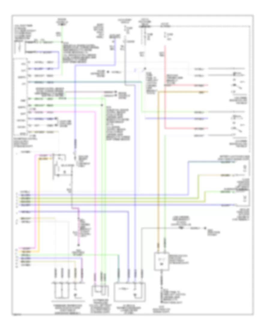
Automatic A/C Wiring Diagram (1 of 2) for Ford Mustang 2010

List of elements for Automatic A/C Wiring Diagram (1 of 2) for Ford Mustang 2010:
- (4.0l: lower left of engine) (4.6l/5.4l: right front of engine)
- (heater blower motor harness, near breakout to floor mode door actuator)
- (on blower motor) blower motor speed control
- (right kick panel)
- (right side of dash) g200
- (right side of engine compt)
- A/c clutch relay
- A/c compressor clutch field coil
- Ambient air temperature sensor (center front of engine compt)
- Ambient temp sensor
- Battery junction box (bjb)
- Blower motor (right side of dash)
- Blower motor relay
- Blower relay
- C2185
- C2280a
- C2280e
- C294a
- C294b
- Ch122
- Ch123
- Ch202
- Ch203
- Ch207
- Ch208
- Ch212
- Ch213
- Ch228
- Ch229
- Ch238
- Ch239
- Ch402
- Ch426
- Chs29
- Chs30
- Computer data lines system
- Defogger system
- Defrost request
- Driv htd seat req
- Driv temp act fdbk
- Driv temp door ccw
- Driv temp door cw
- Driver sunload
- Driver temperature blend door actuator (left side of evaporator assembly)
- Evap temp sensor
- Evaporator discharge air temperature sensor (right side of evaporator assembly)
- Fuse 10a
- Fuse 30a
- Fuse 5a
- G100 (right front of engine compt)
- G201 (right side of dash)
- Gd114
- Gd116
- Gnd
- Hot at all times
- Hot in run or acc
- Hvac module
- In car temp sensor
- Lh111
- Mode 1 act fdbk
- Mode door 1 ccw
- Mode door 1 cw
- Mode door 2 ccw
- Mode door 2 cw
- Mot-
- Ms can+
- Ms can-
- Panel/defrost mode door actuator (right side of dash)
- Pass htd seat req
- Pass temp act fdbk
- Pass temp door ccw
- Pass temp door cw
- Passenger sunload
- Power distribution system
- Pwm
- Recirc ccw
- Recirc cw
- Red
- Return
- Rh111
- S112 (dash panel to headlight junction harness, near breakout to right headlight)
- S130 (body main harness, near breakout to powertrain control module)
- S202 (main harness, near breakout to audio unit)
- S203 (main harness, near breakout to panel/defrost mode door actuator)
- S211 (heater blower motor harness, near breakout to c212)
- S211 (main harness, near breakout to right footwell light)
- S218 (heater blower motor harness, near breakout to driver temperature blend door actuator)
- S219
- Sbp15
- Seats system
- Smart junction box (sjb)
- Variable blwr ctrl
- Vbatt
- Vdb06
- Vdb07
- Vh101
- Vh406
- Vh407
- Vh414
- Vh416
- Vh417
- Vh436
- Vh440
- Vh441
- Vref
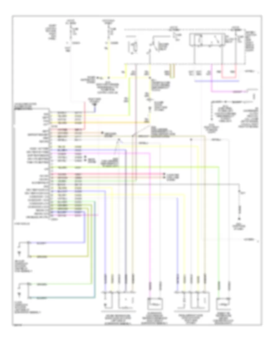
Automatic A/C Wiring Diagram (2 of 2) for Ford Mustang 2010
List of elements for Automatic A/C Wiring Diagram (2 of 2) for Ford Mustang 2010:
- (4.0l: engine control sensor & fuel charge harness, near breakout to turbine shaft speed sensor)
- (4.6l: right rear of engine) (5.4l: rear of right cylinder bank) cylinder head temperature sensor
- (body main harness, near breakout to c192) s121
- (engine control sensor & fuel charge harness, near breakout to bussed electrical center) s103
- (main harness, near breakout to audio control module) s200
- (right kick panel)
- 4.6l
- 5.4l
- A/c pressure transducer (4.0l/4.6l: left front of engine compt) (5.4l: right front of engine compt)
- Accr
- Acpt
- Air inlet mode door actuator (center of hvac assembly)
- Autolamp sensor in
- Battery junction box (bjb) (right side of engine compt)
- C175b
- C175e
- C2280b
- Cec01
- Cec02
- Ch302
- Cht
- Computer data lines system
- Engine controls system
- Engine cooling fan motor (right front of engine compt)
- Floor mode door actuator (left side of evaporator assembly)
- Footwell light)
- Fuse 40a
- Fuse 5a
- G100 (right front of engine compt)
- G200 (right side of dash)
- G201 (right side of dash)
- Harness, near breakout to g100)
- Hfc
- High speed engine cooling fan relay
- Hot at all times
- Hot in start or run
- Hot w/ pcm power relay energized
- Hs can+
- Hs can-
- In-vehicle temperature sensor (lower center of dash)
- Le423
- Lfc
- Low speed engine cooling fan relay
- Nca
- Passenger temperature blend door actuator (right side of evaporator assembly)
- Power distribution system
- Powertrain control module (pcm) (right front of engine compt)
- Re405
- Right headlight)
- S102 (shelby/4.6l: engine control sensor & fuel charge harness, near breakout to heated oxygen sensor #21/12)
- S125 (dash panel to headlight junction
- Sigrtn
- Smart junction box (sjb)
- Solid state
- Sunload sensor (top center of dash)
- Vdb04
- Vdb05
- Ve712
- Vh433
- Vref
Manual A/C Wiring Diagram (1 of 2) for Ford Mustang 2010
List of elements for Manual A/C Wiring Diagram (1 of 2) for Ford Mustang 2010:
- (4.0l: lower left of engine) (4.6l/5.4l: right front of engine)
- (on blower motor) blower motor speed control
- (right kick panel)
- (right side of dash) g200
- (right side of engine compt)
- A/c clutch relay
- A/c compressor clutch field coil
- Air inlet mode door actuator (center of hvac assembly)
- Ambient air temperature sensor (center front of engine compt)
- Battery junction box (bjb)
- Blower motor (right side of dash)
- Blower motor relay
- Blower relay
- C2185
- C2280a
- C2280e
- C294a
- Ch122
- Ch123
- Ch202
- Ch203
- Ch207
- Ch208
- Ch228
- Ch229
- Ch238
- Ch239
- Ch402
- Ch426
- Chs29
- Chs30
- Computer data lines system
- Defogger system
- Defrost request
- Driv htd seat req
- Driv temp act fdbk
- Driv temp door ccw
- Driv temp door cw
- Driver temperature blend door actuator (left side of evaporator assembly)
- Evap temp sensor
- Evaporator discharge air temperature sensor (right side of evaporator assembly)
- Floor mode door actuator (left side of evaporator assembly)
- Fuse 10a
- Fuse 30a
- Fuse 5a
- G100 (right front of engine compt)
- G201 (right side of dash)
- Gd114
- Gd116
- Gnd
- Hot at all times
- Hot in run or acc
- Hvac module
- Lh111
- Mode 1 act fdbk
- Mode door 1 ccw
- Mode door 1 cw
- Mode door 2 ccw
- Mode door 2 cw
- Mot-
- Ms can+
- Ms can-
- Oat
- Panel/defrost mode door actuator (right side of dash)
- Pass htd seat req
- Power distribution system
- Pwm
- Recirc ccw
- Recirc cw
- Red
- Return
- Rh111
- S112 (dash panel to headlight junction harness, near breakout to right headlight)
- S130 (body main harness, near breakout to powertrain control module)
- S202 (main harness, near breakout to audio unit)
- S203 (main harness, near breakout to panel/defrost mode door actuator)
- S211
- S211 (heater blower motor harness, near breakout to c212)
- Sbp15
- Seats system
- Smart junction box (sjb)
- Variable blwr ctrl
- Vbatt
- Vdb06
- Vdb07
- Vh101
- Vh406
- Vh407
- Vh436
- Vh440
- Vref
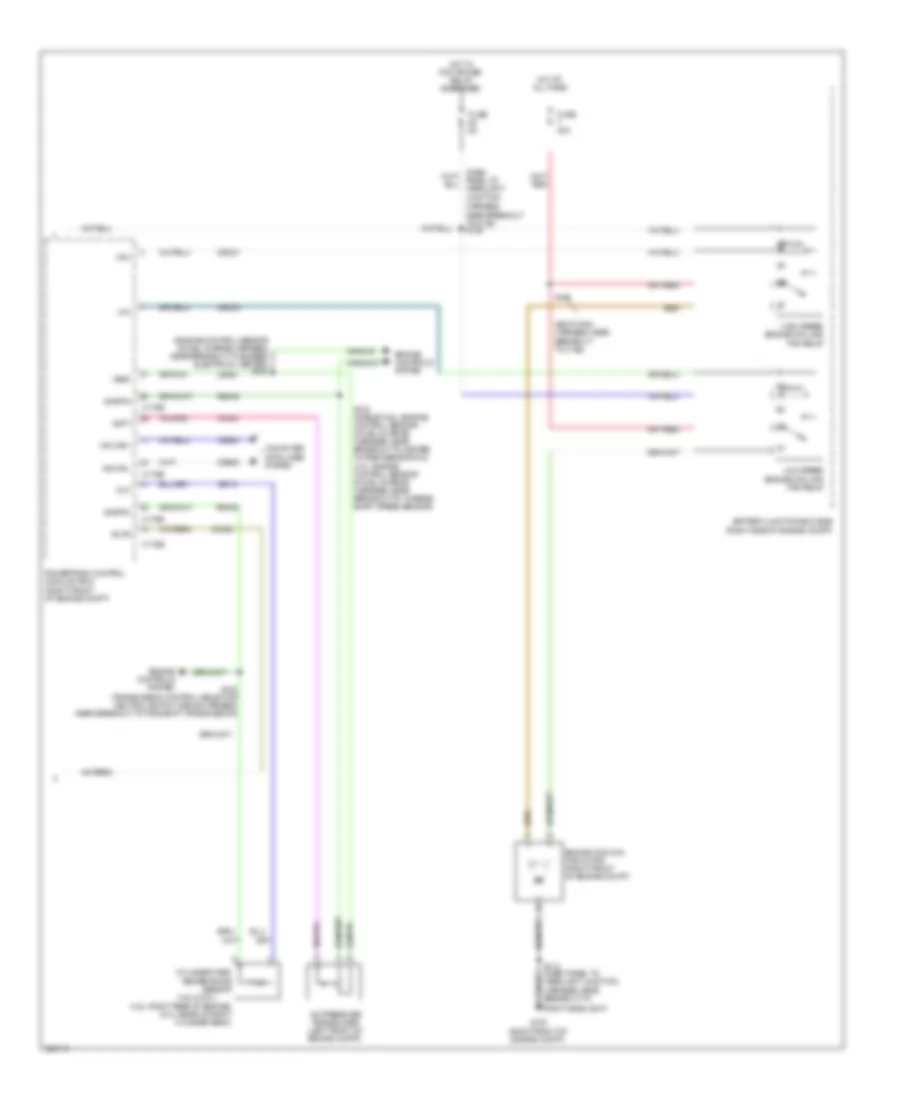
Manual A/C Wiring Diagram (2 of 2) for Ford Mustang 2010
List of elements for Manual A/C Wiring Diagram (2 of 2) for Ford Mustang 2010:
- (4.0l: engine control sensor & fuel charge harness, near breakout to turbine shaft speed sensor)
- (4.6l & 5.4l)
- (4.6l: right rear of engine) (5.4l; rear of right cylinder bank)
- (body main harness, near breakout to c192)
- (engine control sensor & fuel charge harness, near breakout to bussed electrical center) s103
- A/c pressure transducer (left front of engine compt)
- Accr
- Acpt
- Battery junction box (bjb) (right side of engine compt)
- C175b
- C175e
- Cec01
- Cec02
- Ch302
- Cht
- Computer data lines system
- Cylinder head temperature sensor
- Engine controls system
- Engine cooling fan motor (right front of engine compt)
- Fuse 40a
- Fuse 5a
- G100 (right front of engine compt)
- Harness, near breakout to g100) s125
- Hfc
- High speed engine cooling fan relay
- Hot at all times
- Hot w/ pcm power relay energized
- Hs can+
- Hs can-
- Le423
- Lfc
- Low speed engine cooling fan relay
- Powertrain control module (pcm) (right front of engine compt)
- Re405
- Right headlight)
- S102 (shelby/4.6l: engine control sensor & fuel charge harness, near breakout to heated oxygen sensor #12)
- S102 (transmission control selector neutral switch wiring harness, near breakout to torqshift transmission)
- S121
- Sigrtn
- Vdb04
- Vdb05
- Ve712
- Vh433
- Vref