AIR CONDITIONING
4.0L
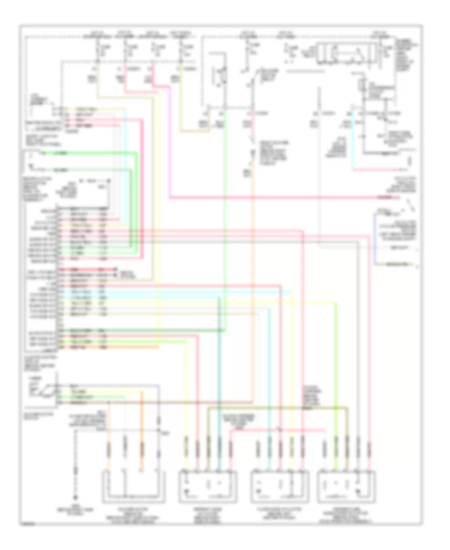
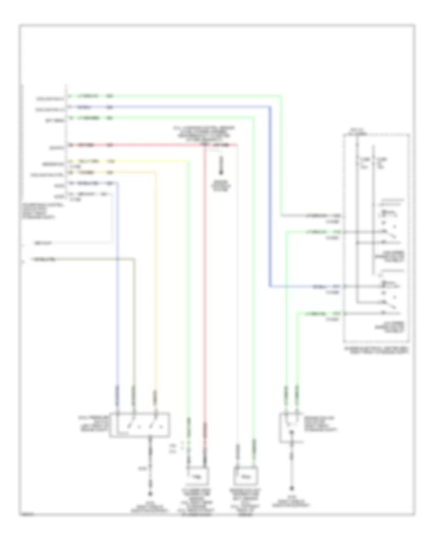
4.0L, Manual A/C Wiring Diagram (1 of 2) for Ford Mustang GT 2008

List of elements for 4.0L, Manual A/C Wiring Diagram (1 of 2) for Ford Mustang GT 2008:
- (in main harness, near breakout to audio unit) s202
- (in main harness, near breakout to audio unit) s203
- (right front of engine compt)
- A/c clu req
- A/c clutch cycling pressure switch (left rear corner of engine compt)
- A/c clutch field coil (lower left side of engine)
- A/c clutch relay
- A/c compressor clutch diode
- A/c request
- Blend dr act
- Blower motor relay
- Blower motor resistor (behind right side of dash, in a/c heater plenum)
- Blower motor switch
- Blwr mtr rly
- Bussed electrical center (bec)
- C1035a e2
- C1035b f8
- C2280a
- C2280b
- C2280h
- Climate control module (behind center of dash)
- Def mode act
- Defrost mode actuator (behind right side of dash)
- Driv htd seat
- Floor mode actuator (behind left center of dash)
- Flr mode act
- Front blower motor (behind right side of dash, in a/c heater plenum)
- Fuse 10a
- Fuse 15a
- Fuse 30a
- Fuse 5a
- G200 (behind right side of dash)
- G201 (behind right side of dash)
- Ground
- Heated backlite
- High
- Hot at all times
- Hot in run or acc
- Hot in start or run
- Illum
- Low
- Low current board
- Pass htd seat
- Pnk
- Rear def ind
- Rear def sw
- Recirc dr mtr
- Recirculation door motor (behind dash,on evaporator assembly)
- Red
- S112
- S200
- S201
- S211 (in heater blower motor harness, near breakout to c212)
- Seats system
- Smart junction box (sjb) (right kick panel)
- Support) g100
- Temperature blend door actuator (behind dash, on evaporator assembly)
- V batt
- V ign
- Vref
- Vref gnd
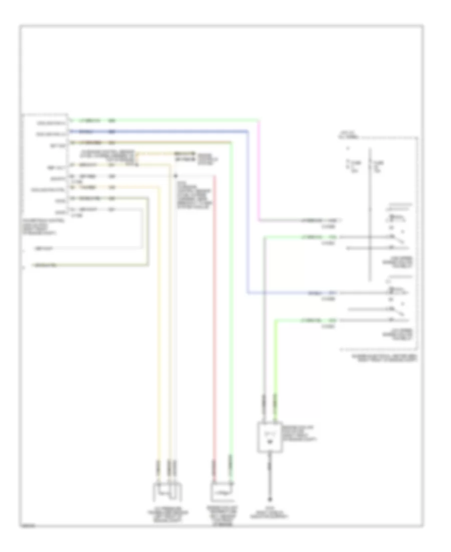
4.0L, Manual A/C Wiring Diagram (2 of 2) for Ford Mustang GT 2008
List of elements for 4.0L, Manual A/C Wiring Diagram (2 of 2) for Ford Mustang GT 2008:
- (in engine control sensor & fuel charge harness, on top of engine) s103
- A/c pressure transducer sensor (left front of engine compt)
- A12
- Accr
- Accs
- Bussed electrical center (bec) (right front of engine compt)
- C1035b
- C1035c
- C11
- C12
- C175b
- C175e
- Cooling fan ctrl
- Cooling fan hi
- Cooling fan lo
- Ect sig
- Engine controls system
- Engine coolant temperature (ect) sensor (top front of engine)
- Engine cooling fan motor (right front of engine compt)
- F12
- Fuse 15a
- Fuse 40a
- G100 (right side of radiator support)
- High speed engine cooling fan relay
- Hot at all times
- Low speed engine cooling fan relay
- Powertrain control module (pcm) (right front of engine compt)
- Ref volt
- S102 (in engine control sensor & fuel charge harness, near breakout to egr system module)
- Sig rtn
- Tan/red
4.6L
4.6L, Manual A/C Wiring Diagram (1 of 2) for Ford Mustang GT 2008
List of elements for 4.6L, Manual A/C Wiring Diagram (1 of 2) for Ford Mustang GT 2008:
- (in main harness, behind center of dash) s202
- (in main harness, behind center of dash) s203
- (right front of engine compt)
- (right side of radiator support) g100
- A/c clutch
- A/c clutch cycling pressure switch (left rear corner of engine compt)
- A/c clutch field coil (right front side of engine)
- A/c clutch relay
- A/c compressor clutch diode
- A/c request
- Blend dr act
- Blower motor relay
- Blower motor resistor (behind right side of dash, in a/c heater plenum)
- Blower motor switch
- Blwr mtr rly
- Bussed electrical center (bec)
- C1035a c1
- C1035a e2
- C1035b f8
- C2280a
- C2280b
- C2280h
- Climate control module (behind center of dash)
- Def mode act
- Defrost mode actuator (behind right side of dash)
- Driv htd seat
- Floor mode actuator (behind left center of dash)
- Flr mode act
- Front blower motor (behind right side of dash, in a/c heater plenum)
- Fuse 10a
- Fuse 15a
- Fuse 30a
- Fuse 5a
- G200 (behind right side of dash)
- G201 (behind right side of dash)
- Ground
- Heated backlite
- High
- Hot at all times
- Hot in run or acc
- Hot in start or run
- Illum
- Low
- Low current board
- Pass htd seat
- Pnk
- Rear def ind
- Rear def sw
- Recirc dr mtr
- Recirculation door motor (behind dash, on evaporator assembly)
- Red
- S100 (4.6l: in engine harness near s119)
- S112
- S200
- S201
- S211 (in heater blower motor harness, near breakout to c212)
- Seats system
- Smart junction box (sjb) (right kick panel)
- Temperature blend door actuator (behind dash, on evaporator assembly)
- V batt
- V ign
- Vref
- Vref gnd
4.6L, Manual A/C Wiring Diagram (2 of 2) for Ford Mustang GT 2008
List of elements for 4.6L, Manual A/C Wiring Diagram (2 of 2) for Ford Mustang GT 2008:
- (5.4l: in engine control sensor & fuel charge harness, near breakout to heated oxygen sensor 21) s102
- 4.6l
- 5.4l
- A12
- Accr
- Accs
- Bussed electrical center (bec) (right front of engine compt)
- C1035b
- C1035c
- C11
- C12
- C175b
- C175e
- Cooling fan ctrl
- Cooling fan hi
- Cooling fan lo
- Cylinder head temperature sensor (4.6l: right rear of engine) (5.4l: rear of right cylinder bank)
- Dual pressure switch (left front of engine compt)
- Ect sens
- Engine controls system
- Engine coolant temperature (ect) sensor (5.4l) (5.4l: top right front of engine)
- Engine cooling fan motor (right front of engine compt)
- F12
- Fuse 15a
- Fuse 40a
- G100 (right side of radiator support)
- High speed engine cooling fan relay
- Hot at all times
- Low speed engine cooling fan relay
- Nca
- Powertrain control module (pcm) (right front of engine compt)
- S100
- Sensor sig
- Sig rtn
- Tan/red
5.4L SUPERCHARGED
5.4L Supercharged, Manual A/C Wiring Diagram (1 of 2) for Ford Mustang GT 2008
List of elements for 5.4L Supercharged, Manual A/C Wiring Diagram (1 of 2) for Ford Mustang GT 2008:
- (in main harness, behind center of dash) s202
- (in main harness, behind center of dash) s203
- (right front of engine compt)
- (right side of radiator support) g100
- A/c clutch
- A/c clutch cycling pressure switch (left rear corner of engine compt)
- A/c clutch field coil (right front side of engine)
- A/c clutch relay
- A/c compressor clutch diode
- A/c request
- Blend dr act
- Blower motor relay
- Blower motor resistor (behind right side of dash, in a/c heater plenum)
- Blower motor switch
- Blwr mtr rly
- Bussed electrical center (bec)
- C1035a c1
- C1035a e2
- C1035b f8
- C2280a
- C2280b
- C2280h
- Climate control module (behind center of dash)
- Def mode act
- Defrost mode actuator (behind right side of dash)
- Driv htd seat
- Floor mode actuator (behind left center of dash)
- Flr mode act
- Front blower motor (behind right side of dash, in a/c heater plenum)
- Fuse 10a
- Fuse 15a
- Fuse 30a
- Fuse 5a
- G200 (behind right side of dash)
- G201 (behind right side of dash)
- Ground
- Heated backlite
- High
- Hot at all times
- Hot in run or acc
- Hot in start or run
- Illum
- Low
- Low current board
- Pass htd seat
- Pnk
- Rear def ind
- Rear def sw
- Recirc dr mtr
- Recirculation door motor (behind dash, on evaporator assembly)
- Red
- S100 (4.6l: in engine harness near s119)
- S112
- S200
- S201
- S211 (in heater blower motor harness, near breakout to c212)
- Seats system
- Smart junction box (sjb) (right kick panel)
- Temperature blend door actuator (behind dash, on evaporator assembly)
- V batt
- V ign
- Vref
- Vref gnd
5.4L Supercharged, Manual A/C Wiring Diagram (2 of 2) for Ford Mustang GT 2008
List of elements for 5.4L Supercharged, Manual A/C Wiring Diagram (2 of 2) for Ford Mustang GT 2008:
- (5.4l: in engine control sensor & fuel charge harness, near breakout to heated oxygen sensor 21) s102
- 4.6l
- 5.4l
- A12
- Accr
- Accs
- Bussed electrical center (bec) (right front of engine compt)
- C1035b
- C1035c
- C11
- C12
- C175b
- C175e
- Cooling fan ctrl
- Cooling fan hi
- Cooling fan lo
- Cylinder head temperature sensor (4.6l: right rear of engine) (5.4l: rear of right cylinder bank)
- Dual pressure switch (left front of engine compt)
- Ect sens
- Engine controls system
- Engine coolant temperature (ect) sensor (5.4l) (5.4l: top right front of engine)
- Engine cooling fan motor (right front of engine compt)
- F12
- Fuse 15a
- Fuse 40a
- G100 (right side of radiator support)
- High speed engine cooling fan relay
- Hot at all times
- Low speed engine cooling fan relay
- Nca
- Powertrain control module (pcm) (right front of engine compt)
- S100
- Sensor sig
- Sig rtn
- Tan/red