AIR CONDITIONING
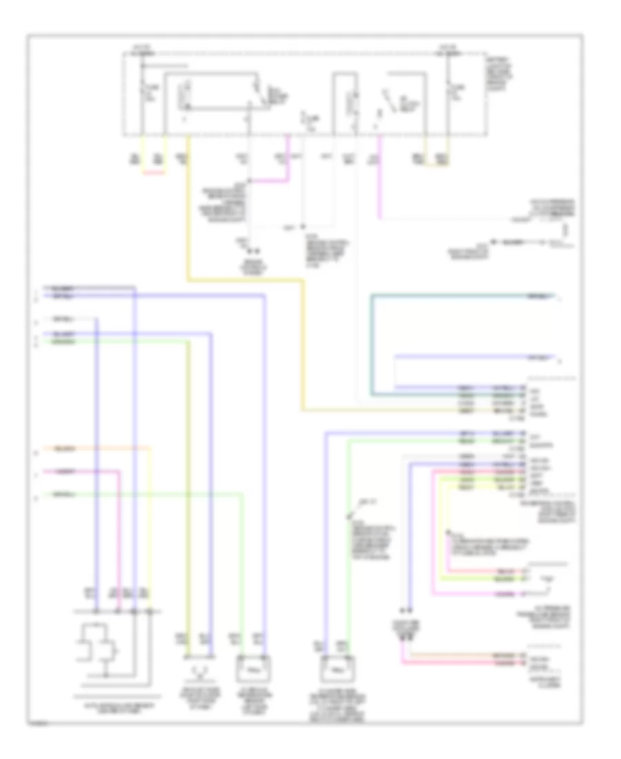
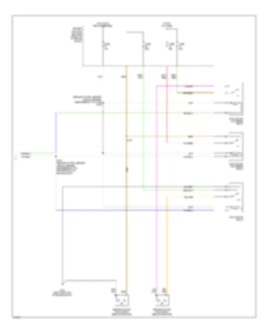
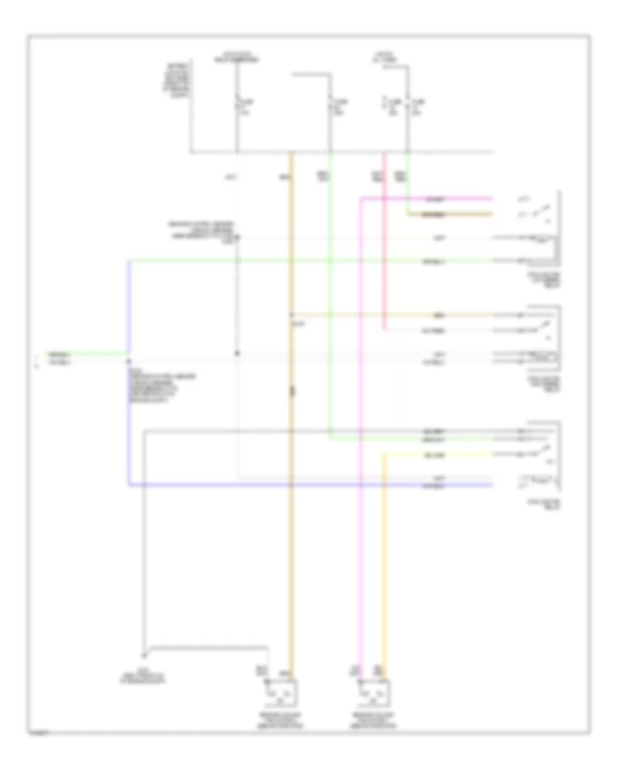
Automatic A/C Wiring Diagram, with Navigation (1 of 3) for Ford Pickup F150 2010

List of elements for Automatic A/C Wiring Diagram, with Navigation (1 of 3) for Ford Pickup F150 2010:
- (front of engine compt) ambient air temperature sensor
- (left side of dash) g203
- (right side of dash) blower motor
- 40a
- Act fdbk
- Ambient temp sen
- Autolamp sensor in
- Battery junction box (bjb) (front of engine compt)
- Blower control
- Blower motor relay
- Blower motor speed control (right side of dash)
- Blower relay
- C2280a
- C2280b
- C2280e
- C228a
- C228b
- Ch122
- Ch123
- Ch207
- Ch208
- Ch212
- Ch213
- Ch228
- Ch229
- Ch238
- Ch239
- Chs04
- Chs09
- Chs13
- Chs14
- Chs29
- Chs30
- Computer data lines system
- Datc hvac module
- Defogger system
- Defrost req
- Defrost status
- Defrost/panel/floor mode actuator (center of dash)
- Door ccw
- Door cw
- Driver sunload
- Drv seat req
- Evap temp sensor
- Evaporative temperature sensor (right side of dash)
- Fuse
- Fuse 10a
- Fuse 5a
- G202 (left side of dash)
- Gd133
- Gnd
- High status
- Hot at all times
- Hot in run or acc
- In car temp sen
- Left temperature blend door actuator (center of dash)
- Lh111
- Low status
- Mode 1 act fdbk
- Mode door 1ccw
- Mode door 1cw
- Motor +
- Motor -
- Ms can+
- Ms can-
- Pass door ccw
- Pass door cw
- Pass seat req
- Pass sunload
- Pass temp act
- Pwm
- Recirc ccw
- Recirc cw
- Return
- Rh111
- Right temperature blend door actuator (right side of dash)
- S200
- S208 (heater blower motor wiring harness, in breakout to center of dash)
- S209 (heater blower motor wiring harness, near breakout to center of dash)
- S228 (main wiring harness, near breakout to right side of dash)
- S229 (main wiring harness, near breakout to c263)
- Sbp15
- Seats system
- Smart junction box (sjb) (right kick panel)
- Vbatt
- Vdb06
- Vdb07
- Vh101
- Vh406
- Vh407
- Vh414
- Vh416
- Vh417
- Vh436
- Vh440
- Vh441
- Vref
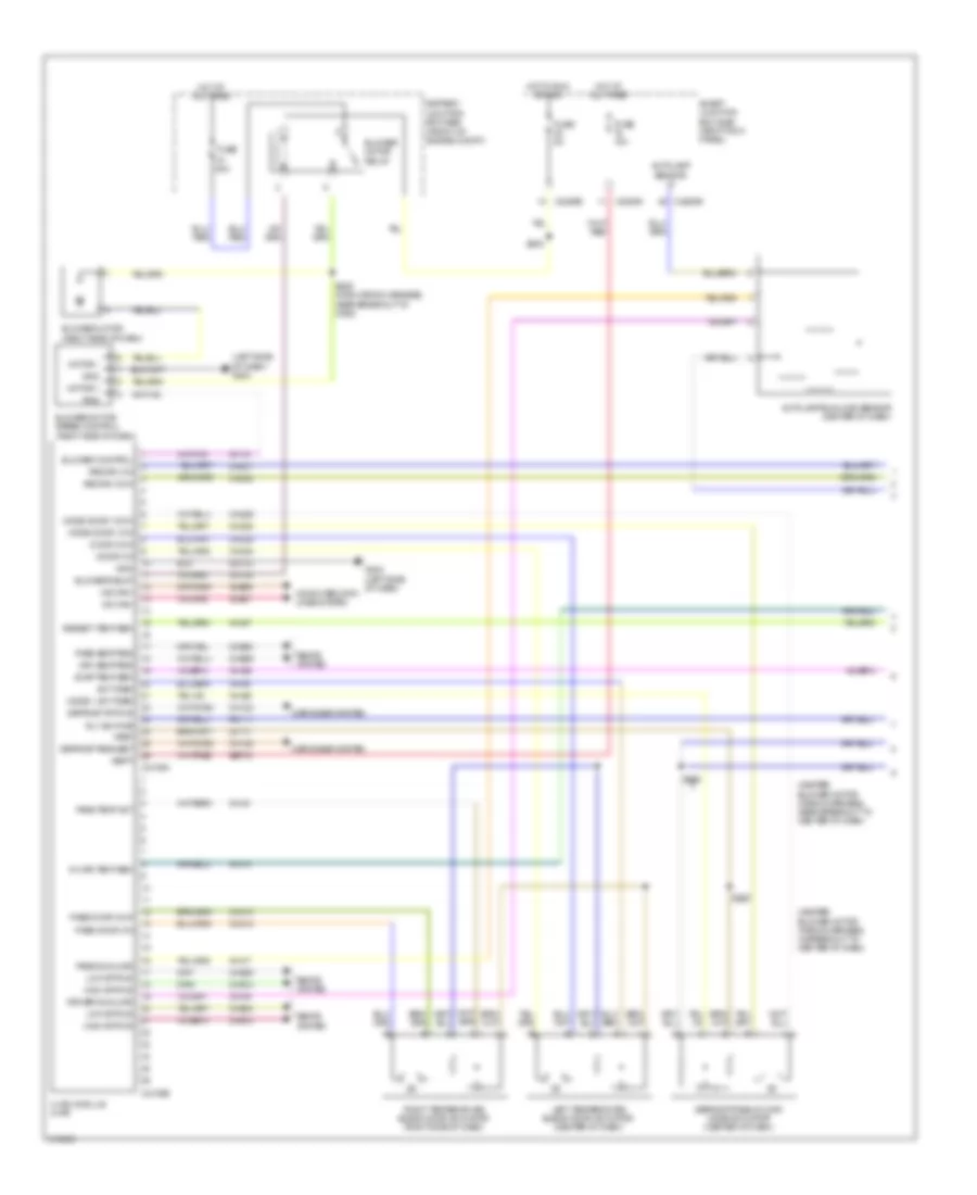
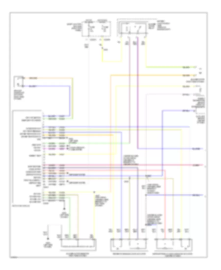
Automatic A/C Wiring Diagram, with Navigation (2 of 3) for Ford Pickup F150 2010
List of elements for Automatic A/C Wiring Diagram, with Navigation (2 of 3) for Ford Pickup F150 2010:
- (a/c compressor) a/c compressor clutch field coil
- 4.6l 2v
- A/c clutch relay
- A/c pressure transducer sensor (right front of engine compt)
- Accr
- Acpt
- Air inlet mode door actuator (right side of dash)
- Autolamp/sunload sensor (center of dash)
- Battery junction box (bjb) (front of engine compt)
- C175b
- C175e
- Ce202
- Ce607
- Cec01
- Ch302
- Cht
- Computer data lines system
- Cylinder head temperature sensor (4.6l 2v: front of left cylinder head) (4.6l 3v & 5.4l: rear of right cylinder head)
- E sig rtn
- Engine controls system
- Fuse 10a
- Fuse 40a
- G101 (right front of engine compt)
- Hfc
- Hot at all times
- Hs can +
- Hs can -
- In vehicle temperature sensor (left side of dash)
- Instrument cluster
- Le424
- Lfc
- Ms can+
- Ms can-
- Pcm power relay
- Pcmrc
- Powertrain control module (pcm) (right rear of engine compt)
- Re405
- Re407
- S105 (engine control sensor wiring harness, near breakout to c146)
- S125 (engine control sensor wiring harness, near breakout to center front of engine compt)
- S140 (engine control sensor & fuel charge wiring harness,near breakout to top of engine)
- S142 (alternator rectifier system wiring harness, in breakout to fusible link e)
- Sig rtn
- Vdb04
- Vdb05
- Ve712
- Vh433
- Vref
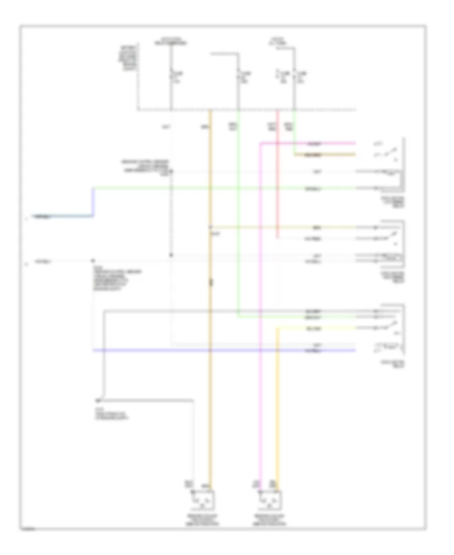
Automatic A/C Wiring Diagram, with Navigation (3 of 3) for Ford Pickup F150 2010
List of elements for Automatic A/C Wiring Diagram, with Navigation (3 of 3) for Ford Pickup F150 2010:
- (engine control sensor wiring harness, near breakout to c146) s105
- Battery junction box (bjb) (front of engine compt)
- Cooling fan high speed relay
- Cooling fan low speed relay
- Cooling fan relay
- Engine cooling fan motor 1 (behind radiator)
- Engine cooling fan motor 2 (behind radiator)
- Fuse 10a
- Fuse 25a
- Fuse 40a
- G101 (right front of of engine compt)
- Hot at all times
- Hot w/ pcm relay energized
- S183 (engine control sensor wiring harness, near breakout to center front of engine compt)
- S197
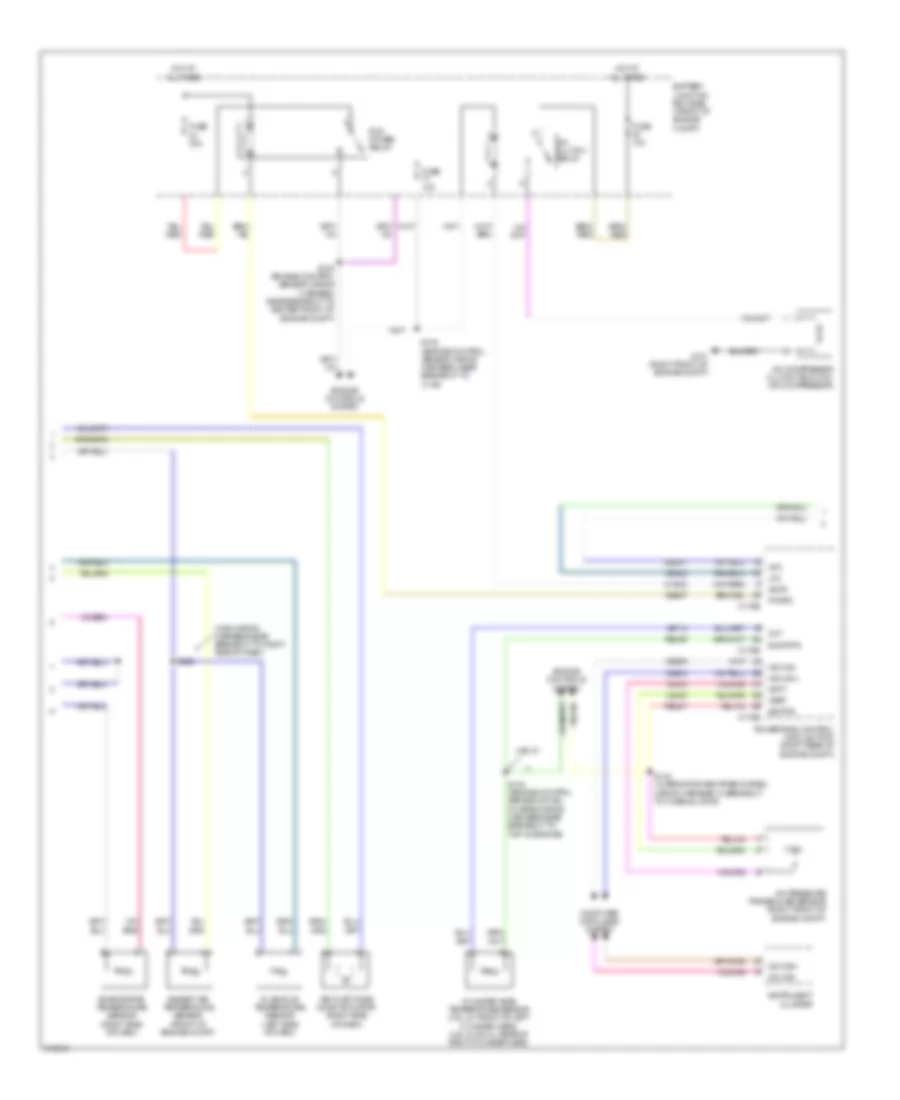
Automatic A/C Wiring Diagram, without Navigation (1 of 3) for Ford Pickup F150 2010
List of elements for Automatic A/C Wiring Diagram, without Navigation (1 of 3) for Ford Pickup F150 2010:
- (heater blower motor wiring harness, in breakout to center of dash)
- (heater blower motor wiring harness, near breakout to center of dash)
- (left side of dash) g203
- 40a
- Act fdbk
- Ambient temp sen
- Autolamp sensor in
- Autolamp/sunload sensor (center of dash)
- Battery junction box (bjb) (front of engine compt)
- Blower control
- Blower motor (right side of dash)
- Blower motor relay
- Blower motor speed control (right side of dash)
- Blower relay
- C2109a
- C2109b
- C2280a
- C2280b
- C2280e
- Ch122
- Ch123
- Ch207
- Ch208
- Ch212
- Ch213
- Ch228
- Ch229
- Ch238
- Ch239
- Chs04
- Chs09
- Chs13
- Chs14
- Chs29
- Chs30
- Computer data lines system
- Defogger system
- Defrost request
- Defrost status
- Defrost/panel/floor mode actuator (center of dash)
- Door ccw
- Door cw
- Driver sunload
- Drv seat req
- Evap temp sen
- Fuse
- Fuse 10a
- Fuse 5a
- G202 (left side of dash)
- Gd133
- Gnd
- High status
- Hot at all times
- Hot in run or acc
- Hvac module datc
- In car temp sen
- Left temperature blend door actuator (center of dash)
- Lh111
- Low status
- Mode 1 act fdbk
- Mode door 1ccw
- Mode door 1cw
- Motor +
- Motor -
- Ms can+
- Ms can-
- Pass door ccw
- Pass door cw
- Pass seat req
- Pass sunload
- Pass temp act
- Pwm
- Recirc ccw
- Recirc cw
- Rh111
- Right temperature blend door actuator (right side of dash)
- Rly sw pwr
- S200
- S208
- S209
- S229 (main wiring harness, near breakout to c263)
- Sbp15
- Seats system
- Smart junction box (sjb) (right kick panel)
- Vbatt
- Vdb06
- Vdb07
- Vh101
- Vh406
- Vh407
- Vh414
- Vh416
- Vh417
- Vh436
- Vh440
- Vh441
- Vref
Automatic A/C Wiring Diagram, without Navigation (2 of 3) for Ford Pickup F150 2010
List of elements for Automatic A/C Wiring Diagram, without Navigation (2 of 3) for Ford Pickup F150 2010:
- (main wiring harness,near breakout to right side of dash)
- 4.6l 2v
- A/c clutch relay
- A/c compressor clutch field coil (a/c compressor)
- A/c pressure transducer sensor (right front of engine compt)
- Accr
- Acpt
- Air inlet mode door actuator (right side of dash)
- Ambient air temperature sensor (front of engine compt)
- Battery junction box (bjb) (front of engine compt)
- C175b
- C175e
- Ce202
- Ce607
- Cec01
- Ch302
- Cht
- Computer data lines system
- Cylinder head temperature sensor (4.6l 2v: front of left cylinder head) (4.6l 3v & 5.4l: rear of right cylinder head)
- E sig rtn
- Engine controls system
- Evaporative temperature sensor (right side of dash)
- Fuse 10a
- Fuse 40a
- G101 (right front of engine compt)
- Hfc
- Hot at all times
- Hs can +
- Hs can -
- In vehicle temperature sensor (left side of dash)
- Instrument cluster
- Le424
- Lfc
- Ms can+
- Ms can-
- Pcm power relay
- Pcmrc
- Powertrain control module (pcm) (right rear of engine compt)
- Re405
- Re407
- S105 (engine control sensor wiring harness, near breakout to c146)
- S125 (engine control sensor wiring harness, near breakout to center front of engine compt)
- S140 (engine control sensor & fuel charge wiring harness,near breakout to top of engine)
- S142 (alternator rectifier system wiring harness, in breakout to fusible link e)
- S228
- Sig rtn
- Vdb04
- Vdb05
- Ve712
- Vh433
- Vref
Automatic A/C Wiring Diagram, without Navigation (3 of 3) for Ford Pickup F150 2010
List of elements for Automatic A/C Wiring Diagram, without Navigation (3 of 3) for Ford Pickup F150 2010:
- (engine control sensor wiring harness, near breakout to c146) s105
- Battery junction box (bjb) (front of of engine compt)
- Cooling fan high speed relay
- Cooling fan low speed relay
- Cooling fan relay
- Engine cooling fan motor 1 (behind radiator)
- Engine cooling fan motor 2 (behind radiator)
- Fuse 10a
- Fuse 25a
- Fuse 40a
- G101 (right front of of engine compt)
- Hot at all times
- Hot w/ pcm relay energized
- S183 (engine control sensor wiring harness, near breakout to center front of engine compt)
- S197
Manual A/C Wiring Diagram (1 of 3) for Ford Pickup F150 2010
List of elements for Manual A/C Wiring Diagram (1 of 3) for Ford Pickup F150 2010:
- (heater blower motor wiring harness, in breakout to center of dash)
- (heater blower motor wiring harness, near breakout to center of dash) s209
- (main wiring harness, near breakout to right side of dash)
- Air inlet mode door actuator (right side of dash)
- Ambient temp
- Ambient temparature sensor (front of engine compt)
- Autolamp sensor (center of dash)
- Battery junction box (bjb) (front of engine compt)
- Blower gnd
- Blower motor (right side of dash)
- Blower motor relay
- Blower motor resistor (right side of dash)
- C2280a
- C2280e
- C294a
- C294b
- Ch122
- Ch123
- Ch207
- Ch208
- Ch228
- Ch229
- Ch238
- Ch239
- Ch426
- Ch428
- Ch429
- Computer data lines system
- Defogger system
- Defrost req
- Defrost status
- Defrost/panel/floor mode door actuator (center of dash)
- Driver temp door ccw
- Driver temp door cw
- Drv htd seat sw
- Drv temp feedback
- Emtc-hvac module
- Evap temp sen
- Front blower rly
- Fuse 10a
- Fuse 5a
- G202 (left side of dash)
- G203 (left side of dash)
- Gd133
- Gd138
- Gnd
- Hot at all times
- Hot in run or acc
- Lh111
- Mode actr b-
- Mode door ccw
- Mode door fdbk
- Ms can+
- Ms can-
- Rear def htd mirror
- Return
- Rh111
- S200
- S208
- S227
- S228
- Sbp15
- Smart junction box (sjb) (right kick panel)
- Sw high
- Sw med high
- Sw med low
- Temperature blend door actuator
- Vbatt
- Vdb06
- Vdb07
- Vh406
- Vh407
- Vh436
- Vh440
- Vref actr
Manual A/C Wiring Diagram (2 of 3) for Ford Pickup F150 2010
List of elements for Manual A/C Wiring Diagram (2 of 3) for Ford Pickup F150 2010:
- A/c clutch relay
- A/c compressor clutch field coil (a/c compressor)
- A/c pressure transducer sensor (right front of engine compt)
- Accr
- Acpt
- Battery junction box (bjb) (front of engine compt)
- C175b
- C175e
- Ce202
- Ce607
- Cec01
- Ch302
- Cht
- Computer data lines system
- Cylinder head temperature sensor (4.6l 2v: front of left cylinder head) (4.6l 3v & 5.4l: rear of right cylinder head)
- E sig rtn
- Engine controls system
- Evaporative temparature sensor (right side of dash)
- Fuse 10a
- Fuse 40a
- G101 (right front of engine compt)
- Hfc
- Hot at all times
- Hs can +
- Hs can -
- Instrument cluster
- Le424
- Lfc
- Ms can+
- Ms can-
- Pcm power relay
- Pcmrc
- Powertrain control module (pcm) (right rear of engine compt)
- Re405
- Re407
- S105 (engine control sensor wiring harness, near breakout to c146)
- S125 (engine control sensor wiring harness, near breakout to center front of engine compt)
- S140 (4.6l 2v) (engine control sensor & fuel charge wiring harness,near breakout to top of engine)
- S142 (alternator rectifier system wiring harness, in breakout to fusible link e)
- Sig rtn
- Vdb04
- Vdb05
- Ve712
- Vh433
- Vref
Manual A/C Wiring Diagram (3 of 3) for Ford Pickup F150 2010
List of elements for Manual A/C Wiring Diagram (3 of 3) for Ford Pickup F150 2010:
- (engine control sensor wiring harness, near breakout to c146) s105
- Battery junction box (bjb) (front of of engine compt)
- Cooling fan high speed relay
- Cooling fan low speed relay
- Cooling fan relay
- Engine cooling fan motor 1 (behind radiator)
- Engine cooling fan motor 2 (behind radiator)
- Fuse 10a
- Fuse 25a
- Fuse 40a
- G101 (right front of of engine compt)
- Hot at all times
- Hot w/ pcm relay energized
- S183 (engine control sensor wiring harness, near breakout to center front of engine compt)
- S197