AIR CONDITIONING
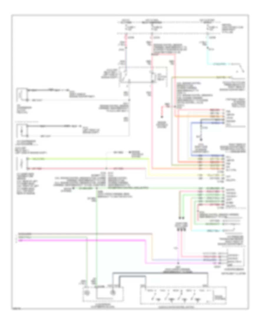
Automatic A/C Wiring Diagram (1 of 2) for Ford Pickup F350 Super Duty 2008

List of elements for Automatic A/C Wiring Diagram (1 of 2) for Ford Pickup F350 Super Duty 2008:
- (heater blower motor wiring harness, in breakout to c299)
- (right front footwell) g203
- Air inlet mode door actuator (behind right side of dash)
- Anti- theft system
- Autolamp/sunload sensor (top left side of dash)
- Blower motor (behind dash)
- Blower motor relay
- Blower motor speed controller (right "a" pillar)
- C228a
- C228b
- C270e
- C270g
- C3008b
- Central junction box (cjb) (near right "a" pillar)
- Control solid state
- Defogger system
- Defrost req
- Defrost/panel/floor mode actuator (behind center of dash)
- Drv hi status
- Drv lo status drv heated seat req
- Feed a
- Feed b
- Feedback
- Fuse 116 30a
- Fuse 13 10a
- Fuse 5 7.5a
- G200 (left "a" pillar)
- Gnd
- High/low
- Hot at all times
- Hot in start or run
- Hvac module (eatc)
- In car temp
- In-vehicle temperature sensor (behind dash panel)
- Interior lights system
- Light sensor
- Mtr ctrl
- Pass hi status
- Pass lo status
- Pats ind
- Red
- Redundant in
- Rly ctrl
- Rly sw pwr
- S202
- S204 (heater blower motor wiring harness, in breakout to c299)
- S208
- S210
- S236
- S286
- Seats system
- Sens
- Sens rtn
- Sig
- Sun sensor
- Sunload sens
- Temperature blend door actuator (behind center of dash)
- Ubp
- Vbatt
- Vbc
- Vbc out
- Vehicle security module (super cab/super crew: left rear of cab) (regular cab: left "b" pillar)
- Vpwr
- Vref
- Vref rtn
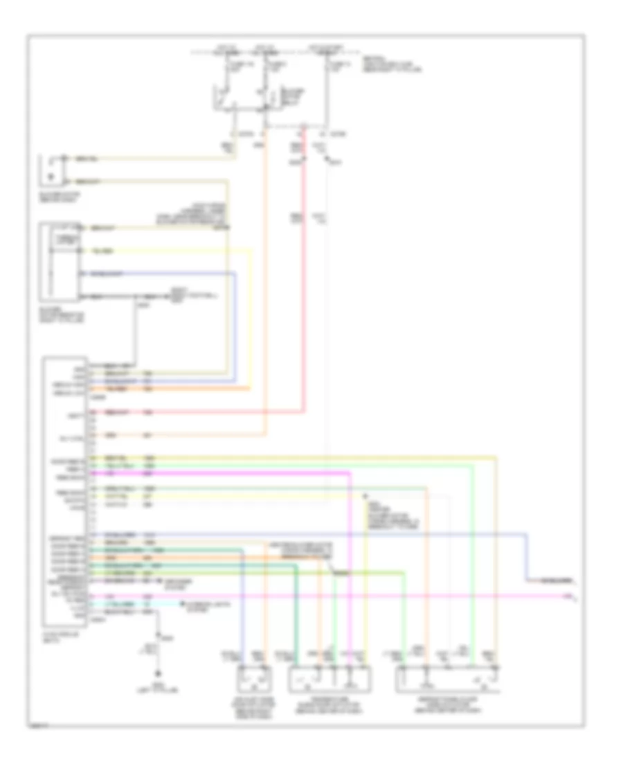
Automatic A/C Wiring Diagram (2 of 2) for Ford Pickup F350 Super Duty 2008
List of elements for Automatic A/C Wiring Diagram (2 of 2) for Ford Pickup F350 Super Duty 2008:
- (4.6l: engine control sensor & fuel charge harness, near breakout to ho2s 11) (5.4l: engine control sensor & fuel charge harness, near breakout to charge motion control valve (cmcv)) s154
- (except 4.2l) (4.6l: engine control sensor & fuel charge harness, near breakout to c139) (5.4l: engine control sensor & fuel charge harness, near breakout to fuel injector 8)
- (right rear of engine compartment) powertrain control module (pcm)
- (top right front of engine) electronic fan clutch
- A/c clutch cycling pressure switch (right rear of engine compartment)
- A/c clutch relay
- A/c compressor clutch diode
- A/c compressor clutch field coil
- A/c pressure transducer sensor (right front of engine compartment)
- Acpt
- Audio/climate control switch
- Auxiliary relay box 1 (left side of engine compt)
- Backlite in
- Bvref
- C175b
- C175e
- C218b
- C220a
- C270a
- C270b
- Can bus +
- Can bus -
- Central junction box (cjb) (near right "a" pillar)
- Cht
- Clockspring (in steering column)
- Computer data lines system
- Cylinder head temperature sensor (4.2l: rear of left cylinder head) (4.6l: front of left cylinder head) (5.4l: top right rear of engine)
- Engine controls system
- Fan+
- Fan-
- Fc-v
- Fss
- Fss-gnd
- Fuse 11 10a
- Fuse 14 10a
- Fuse 32 15a
- G104 (right side of engine compartment)
- G110 (left front of engine compt)
- Hot at all times
- Hot in start or run
- Hot w/ pcm relay energized
- Instrument cluster
- Microprocessor
- Nca
- Rly ctrl
- S101 (engine control sensor harness, near breakout to auxiliary box 1)
- S104 (engine control sensor harness, near breakout to c139)
- S105
- S112
- S116
- S122
- S135 s173 (4.2l) (engine control sensor & fuel charge harness, near breakout to powertrain control module (pcm)
- S281 (main wiring harness, near breakout to c2026)
- Sig
- Sig rtn
- Sig_rtn
- Sound systems
- Temp+
- Temp-
- Ubp
- Vbpwr
- Vpwr
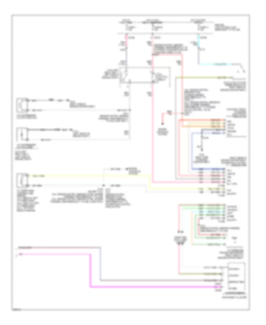
Manual A/C Wiring Diagram (1 of 2) for Ford Pickup F350 Super Duty 2008
List of elements for Manual A/C Wiring Diagram (1 of 2) for Ford Pickup F350 Super Duty 2008:
- (heater blower motor wiring harness, in breakout to c299)
- (main wiring harness, under dash, near breakout to blower motor resistor) s275
- (right front footwell) g203
- Ac req
- Air inlet mode door actuator (behind right side of dash)
- Blower motor (behind dash)
- Blower motor relay
- Blower motor resistor (right "a" pillar)
- C270e
- C270g
- C294a
- C294b
- Central junction box (cjb) (near right "a" pillar)
- Defogger system
- Defrost req
- Defrost/panel/floor mode actuator (behind center of dash)
- Door feed a
- Door feed b
- Feed a
- Feed back
- Feedback rear window defrost rly sw pwr
- Fuse 116 30a
- Fuse 13 10a
- Fuse 5 7.5a
- G200 (left "a" pillar)
- Gnd
- High
- Hot at all times
- Hot in start or run
- Hvac module (emtc)
- Illum
- Interior lights system
- Medium high
- Medium low
- Rly ctrl
- S200
- S202
- S204 (heater blower motor wiring harness, in breakout to c299)
- S208
- S210
- S236
- Sig rtn
- Temperature blend door actuator (behind center of dash)
- Thermal limiter
- Vbatt
- Vpwr
Manual A/C Wiring Diagram (2 of 2) for Ford Pickup F350 Super Duty 2008
List of elements for Manual A/C Wiring Diagram (2 of 2) for Ford Pickup F350 Super Duty 2008:
- (4.6l: engine control sensor & fuel charge harness, near breakout to ho2s 11) (5.4l: engine control sensor & fuel charge harness, near breakout to charge motion control valve (cmcv)) s154
- (except 4.2l) (4.6l: engine control sensor & fuel charge harness, near breakout to c139) (5.4l: engine control sensor & fuel charge harness, near breakout to fuel injector 8)
- (right rear of engine compartment) powertrain control module (pcm)
- (top right front of engine) electronic fan clutch
- A/c clutch cycling pressure switch (right rear of engine compartment)
- A/c clutch relay
- A/c compressor clutch diode
- A/c compressor clutch field coil
- A/c pressure transducer sensor (right front of engine compartment)
- Ac req
- Acpt
- Auxiliary relay box 1 (left side of engine compt)
- Bvref
- C175b
- C175e
- C220a
- C220b
- C270a
- C270b
- Can bus +
- Can bus -
- Central junction box (cjb) (near right "a" pillar)
- Cht
- Computer data lines system
- Cylinder head temperature sensor (4.2l: rear of left cylinder head) (4.6l: front of left cylinder head) (5.4l: top right rear of engine)
- Defrost req
- Engine controls system
- Fc-v
- Fss
- Fss-gnd
- Fuse 11 10a
- Fuse 14 10a
- Fuse 32 15a
- G104 (right side of engine compartment)
- G110 (left front of engine compt)
- Hot at all times
- Hot in start or run
- Hot w/ pcm relay energized
- Instrument cluster
- Microprocessor
- Rly ctrl
- S101 (engine control sensor harness, near breakout to auxiliary box 1)
- S104 (engine control sensor harness, near breakout to c139)
- S105
- S112
- S116
- S122
- S135 s173 (4.2l (engine control sensor & fuel charge harness, near breakout to powertrain control module (pcm)
- Sig
- Sig_rtn
- Vbpwr
- Vpwr