AIR CONDITIONING
Heater Wiring Diagram for Ford Ranger 2000

List of elements for Heater Wiring Diagram for Ford Ranger 2000:
- (main harness, near breakout to radio)
- (top rear of left fender apron) g104
- 87a
- Battery junction box (left rear of engine compartment)
- Blower motor (right rear of engine compartment on firewall)
- Blower motor fuse 40a
- Blower motor relay
- Blower motor resistor assembly (right rear of engine compartment, near blower motor)
- Blower switch
- C233
- C234
- Central junction box (behind left side of dash)
- Defrost
- Floor
- Flr/def
- Function selector switch assembly
- Fuse 7.5a
- High
- Hot at all times
- Hot in run
- Illumi- nation
- Interior lights system
- Low
- Med high
- Med low
- Off
- Panel
- Panel/ floor
- S114 (dash panel to headlamp junction harness, in breakout to blower motor)
- S115 (dash panel to headlamp junction harness, near battery junction box)
- S209
- S212 (main harness, in breakout to generic electronic module (gem))
- S250 (main harness, near breakout to central junction box)
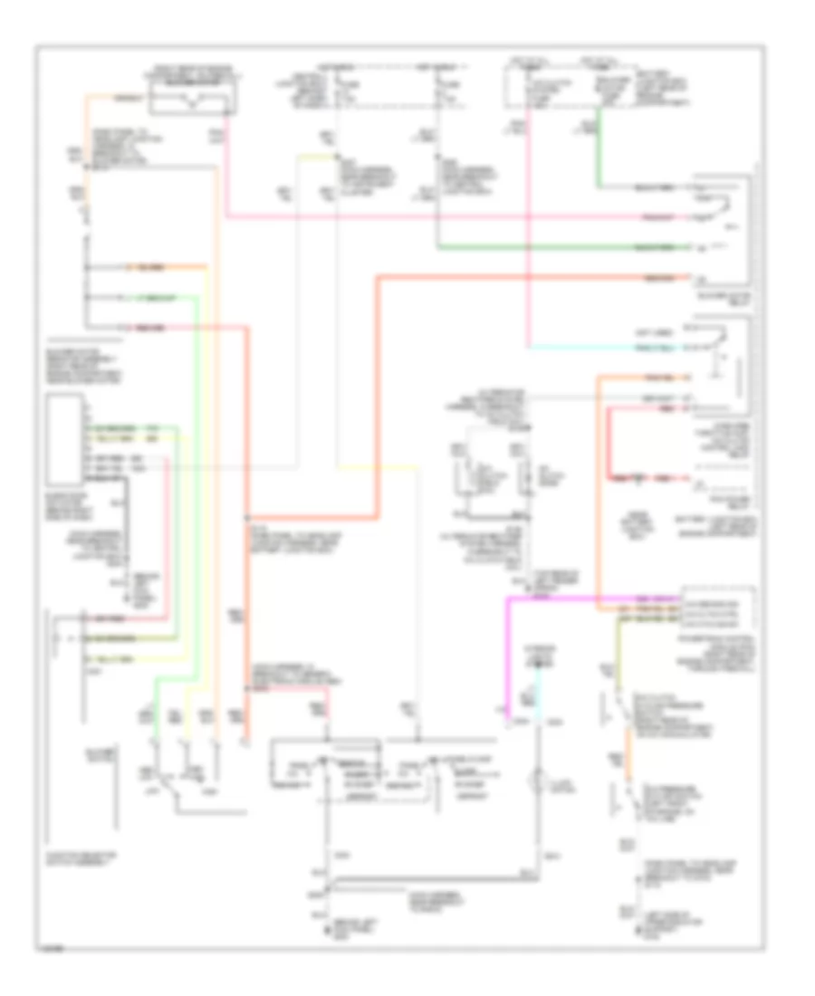
Manual A/C Wiring Diagram for Ford Ranger 2000
List of elements for Manual A/C Wiring Diagram for Ford Ranger 2000:
- (alternator rectifier system harness, in breakout to a/c clutch field coil) s145
- (behind left kick panel) g200
- (dash panel to headlamp junction harness, in breakout to blower motor) s114
- (dash panel to headlamp junction harness, near breakout to g104) s118
- (left side of upper radiator support) g108
- (main harness, in breakout to generic electronic module (gem) s212
- (main harness, near breakout to radio)
- (main harness, near breakout to central junction box) s244
- (near battery junction box)
- (not used)
- (right rear of engine compartment, on firewall) blower motor
- (top rear of left fender apron) g104
- 87a
- A/c
- A/c cltch ctrl
- A/c clutch cycling pressure switch (right rear of engine compartment, on a/c accumulator)
- A/c clutch diode
- A/c clutch field coil
- A/c clutch system fuse 10a
- A/c cycling sw
- A/c demand sig
- A/c pressure cut-off switch (left front of engine, on a/c line)
- Battery junction box (left rear of engine compartment)
- Blend door actuator (behind right side of dash)
- Blower motor fuse 40a
- Blower motor relay
- Blower motor resistor assembly (right rear of engine compartment, near blower motor)
- Blower switch
- C231
- C233
- C234
- Central junction box (behind left side of dash)
- Defrost
- Floor
- Flr/def
- Function selector switch assembly
- Fuse 7.5a
- High
- Hot at all times
- Hot in run
- Illumi- nation
- In breakout to a/c clutch field coil)
- Interior lights system
- Low
- Max a/c
- Med high
- Med low
- Off
- Pan/flr
- Panel
- Panel/floor
- Pcm power relay
- Powertrain control module (pcm) (right rear of engine compartment, through firewall)
- Red
- S115 (dash panel to headlamp junction harness, near battery junction box)
- S121
- S146 (alternator rectifier system harness,
- S209
- S227 (main harness, near breakout to instrument cluster)
- S250 (main harness, near breakout to central junction box)
- Wide open throttle (wot) a/c clutch control (acc) relay
 English