AIR CONDITIONING
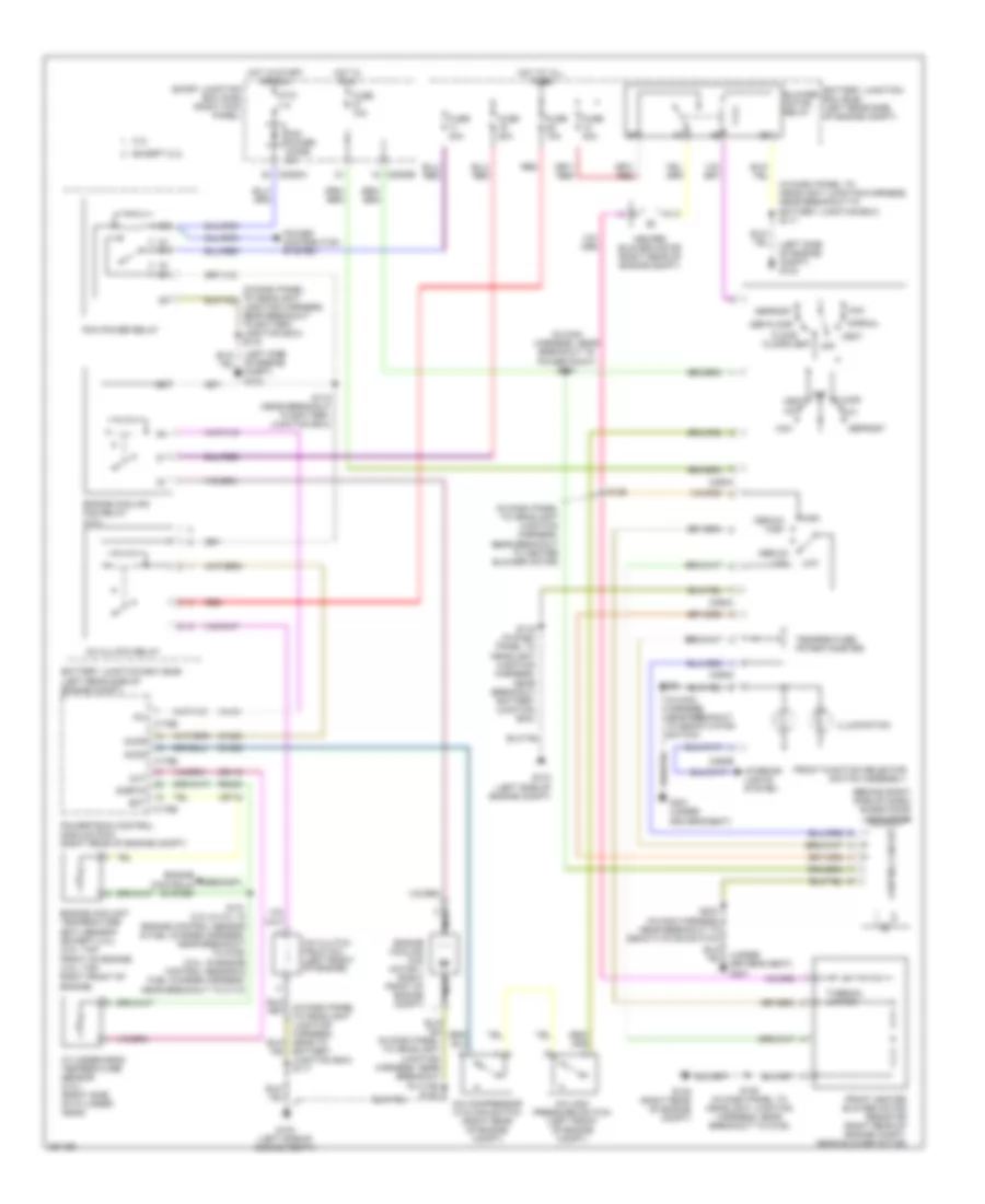
Heater Wiring Diagram for Ford Ranger 2007

List of elements for Heater Wiring Diagram for Ford Ranger 2007:
- (in dash panel to headlight junction harness, near breakout to battery junction box) s117
- (in dash panel to headlight junction harness, near breakout to heater blower motor) s129
- (left side of engine compt) g103
- (not used)
- (right rear of engine compt) heater blower motor
- A/c
- Battery junction box (bjb) (left rear side of engine compt)
- Blend door actuator (behind right side of dash)
- Blower motor relay
- C2280b
- C294a
- C294b
- C294c
- C294d
- Control circuit
- Def/floor
- Defrost
- Floor
- Floor/vent
- Front function selector switch assembly
- Front heater blower motor resistor (right rear of engine compt, near blower motor)
- Fuse 10a
- Fuse 30a
- G103 (left side of engine compt)
- G105 (right rear of engine compt)
- G301 (under driver's seat)
- High
- Hot at all times
- Hot in run
- Illumination
- Interior lights system
- Low
- Max
- Medium high
- Medium low
- Mix
- Normal
- Off
- S128 (in dash panel to headlight junction harness, near breakout to g105)
- S203 (in main harness, near breakout to deactivator switch)
- S216 (in main harness, near breakout to c237)
- S227 (in main harness, near breakout to power point)
- Smart junction box (sjb) (right kick panel)
- Temperature potentiometer
- Thermal limiter
- Vent
Manual A/C Wiring Diagram for Ford Ranger 2007
List of elements for Manual A/C Wiring Diagram for Ford Ranger 2007:
- (behind right side of dash) blend door actuator
- (in dash panel to headlight junction harness, near breakout to battery junction box) s116
- (in dash panel to headlight junction harness, near breakout to battery junction box) s117
- (in dash panel to headlight junction harness, near breakout to heater blower motor)
- (in main harness, near breakout to deactivator switch)
- (in main harness, near breakout to power point) s227
- (left side of engine compt) g103
- (under driver's seat)
- 2.3l
- A/c
- A/c clutch field coil (left front of engine)
- A/c clutch relay
- A/c compressor cycling switch (right rear of engine compt)
- A/c high pressure switch (left front of engine compt)
- Accr
- Accs
- Battery junction box (bjb) (left rear side of engine compt)
- Battery junction box) s117
- Blower motor relay
- C175b
- C175e
- C2280a
- C2280b
- C294a
- C294b
- C294c
- C294d
- Ce116
- Ch302
- Ch425
- Cht
- Control circuit
- Cylinder-head temperature sensor (2.3l) (right side of cylinder head)
- Def/floor
- Defrost
- Ect
- Engine controls system
- Engine coolant temperature (ect) sensor (except 2.3l) (3.0l: top front of engine) (4.0l: top right front of engine)
- Engine cooling fan motor 1 (right front of engine compt)
- Engine cooling fan relay (2.3l)
- Except 2.3l
- Fci
- Floor
- Floor/vent
- Front function selector switch assembly
- Front heater blower motor resistor (right rear of engine compt, near blower motor)
- Fuse 10a
- Fuse 20a
- Fuse 30a
- G103 (left side of engine compt)
- G105 (right rear of engine compt)
- G301
- G301 (under driver's seat)
- Heater blower motor (right rear of engine compt)
- High
- Hot at all times
- Hot in run
- Hot in start or run
- Illumination
- Interior lights system
- Low
- Max
- Medium high
- Medium low
- Mix
- Nca
- Normal
- Of engine compt) g103
- Off
- Pcm power diode 3a
- Pcm power relay
- Power distribution system
- Powertrain control module (pcm) (right rear of engine compt)
- Ptc 1a
- Re405
- Red
- S101 (2.3l & 4.0l: in engine control sensor & fuel charge harness, near breakout to g106) (3.0l: in engine control sensor & fuel charge harness, near breakout to c110)
- S116 (in dash panel to headlight junction harness, near breakout battery junction box)
- S118 (near breakout to battery junction box)
- S128 (in dash panel to headlight junction harness, near breakout to g105)
- S129
- S203
- S203 (in main harness, near breakout to deactivator switch)
- Sigrtn
- Smart junction box (sjb) (right kick panel)
- Temperature potentiometer
- Thermal limiter
- Ve716
- Vent
- Vh101
 English