AIR CONDITIONING
Manual A/C Wiring Diagram, with Stripped Chassis for Ford RV Cutaway E350 Super Duty 2004

List of elements for Manual A/C Wiring Diagram, with Stripped Chassis for Ford RV Cutaway E350 Super Duty 2004:
- (at left rear of engine compt) g113
- (at rear center of engine compt) g114
- (not used)
- A/c clutch field coil (on lower right front of engine)
- A/c compressor clutch diode
- A/c cycling switch
- A/c demand signal
- A/c on input signal
- Battery junction box (bjb) (at left side of engine compartment)
- Blower motor
- Blower motor relay
- Central junction box (cjb) (behind left side of dash)
- Fuse 15a
- Fuse 50a
- Fused blower motor feed
- Hot at all times
- Hot in run
- Powertrain control module (pcm) (at left rear of engine compt)
- S195 (in engine control sensor harness, in breakout to c110)
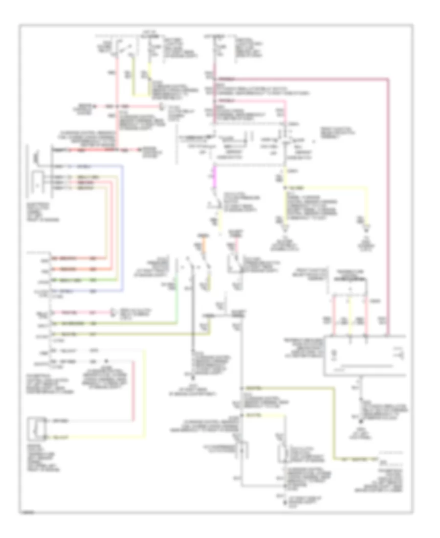
Manual A/C Wiring Diagram, without Stripped Chassis (1 of 2) for Ford RV Cutaway E350 Super Duty 2004
List of elements for Manual A/C Wiring Diagram, without Stripped Chassis (1 of 2) for Ford RV Cutaway E350 Super Duty 2004:
- (at right side of engine compt) g107
- (in engine control sensor & fuel charge wiring harness, near breakout to top center of engine) s1057
- A/c clutch cycling pressure switch (at right rear of engine compt)
- A/c clutch field coil (on lower right front of engine)
- A/c compressor clutch diode
- A/c high pressure switch (in right rear of engine compt)
- A/c sw
- Battery junction box (bjb) (at right rear of engine compt)
- Breakout to c139)
- Breakout to front of engine) s1053
- C176a
- C176c
- C294a
- C294d
- Central junction box box (cjb) (behind left side of dash)
- Clutch ctrl c176c
- Defrost
- Diesel
- Dual pressure switch (at right front of engine compt)
- Electronic fan clutch (diesel) (at left front of engine)
- Engine controls system
- Engine coolant temperature (ect) sensor (diesel) (on upper left front of engine)
- Except diesel
- Floor
- From a/c clutch relay (diagram 2 of 2)
- Front function selector switch assembly
- Fss
- Fuse 15a
- Fuse 30a
- G107 (at right rear of engine compartment)
- G204 (at left kick panel)
- Gnd
- Hot at all times
- Hot in run
- Input
- Max a/c
- Mix
- Mode switch
- Nca
- Norm a/c
- Off
- Pcm power relay
- Powertrain control module (pcm) (at left rear of engine compt, near master brake cylinder)
- Powertrain control module (pcm) (in left rear of engine compt, near brake master cylinder)
- Red
- Relay ctrl
- S1033 (in engine control sensor wiring harness, near breakout to starter relay)
- S1052 (in engine control sensor & fuel charge wiring harness, near breakout to front of engine)
- S1059 (in engine control sensor & fuel charge wiring harness, near breakout to rear left of engine compt)
- S142 (in engine control sensor harness, near breakout to right side of engine compt)
- S203 (in main wiring harness, near breakout to center of dash)
- S223 (in window regulator relay switch harness, near breakout to steering column)
- S242 (in window regulator relay switch harness, near breakout to right side of dash)
- Sig
- Sig rtn
- Temperature blend door actuator (behind right side of dash, on a/c heater plenum)
- Temperature control potentiometer
- To a/c clutch relay (diagram 2 of 2)
- To blower motor relay (diagram 2 of 2)
- To s400 (diagram 2 of 2)
- Vent
- Vent norm a/c
- Vpwr
- Vref
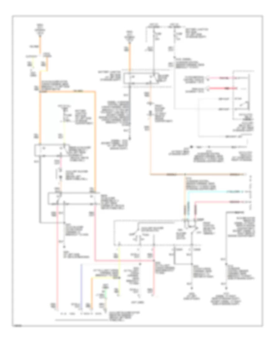
Manual A/C Wiring Diagram, without Stripped Chassis (2 of 2) for Ford RV Cutaway E350 Super Duty 2004
List of elements for Manual A/C Wiring Diagram, without Stripped Chassis (2 of 2) for Ford RV Cutaway E350 Super Duty 2004:
- (diesel)
- (diesel) (except diesel)
- (diesel: in engine control sensor wiring harness, near breakout to trailer tow right turn relay) (except diesel: in engine control sensor wiring harness, near breakout to g105) s1029
- (in tailllight wiring harness, near breakout to c925) s303
- (not used)
- 87a
- A/c clutch field coil (at lower right front of engine)
- A/c clutch relay (diesel)
- Auxiliary blower motor (behind left rear wheelwell)
- Auxiliary blower motor resistor assembly (behind left rear wheelwell)
- Auxiliary blower motor switch
- Auxiliary relay box 1 (at left rear of engine compt)
- Battery junction box (bjb) (at left side of engine compartment)
- Battery junction box (bjb) (at left side of engine compt)
- Blower motor relay
- Blower motor resistor (diesel: at right rear of engine compartment) (except diesel: in right rear of engine compartment)
- Blower motor switch
- C294b
- C294c
- Cutaway
- From s111 (diagram 1 of 2)
- From s142 (diagram 1 of 2)
- Front blower motor (at right rear of engine compartment)
- Front function selector switch assembly
- Fuse 10a
- Fuse 50a
- G100 g105 (at left rear of engine compt)
- G107 (at right rear of engine compt)
- G107 (diesel: at right rear of engine compt) (except diesel: at right side of engine compt)
- G202 (at left side of dash)
- G400 (at left side of vehicle rear end)
- High
- Hot at all times
- Low
- Of rear seats) s400
- Off
- Rear a/c blower speed relay 1 (in left rear corner of vehicle, above wheelwell)
- Rear a/c blower speed relay 2 (in left rear corner of vehicle, above wheelwell)
- Red
- S143 (in engine control sensor harness, near breakout to right side of engine compartment)
- S143 (in engine control sensor harness, near breakout to right side of engine compt)
- S144 (in engine control sensor harness, near breakout to right side of engine compartment)
- S145
- S202 (in main wiring harness, near breakout to center of dash)
- S304 (in taillight wiring harness, near breakout to c925)
- S305 (in taillight wiring harness, near breakout to c925)
- S401 (in a/c blower motor wiring harness, in breakout to c405)
- To powertrain control module (diagram 1 of 2)
- Van & wagon