AIR CONDITIONING
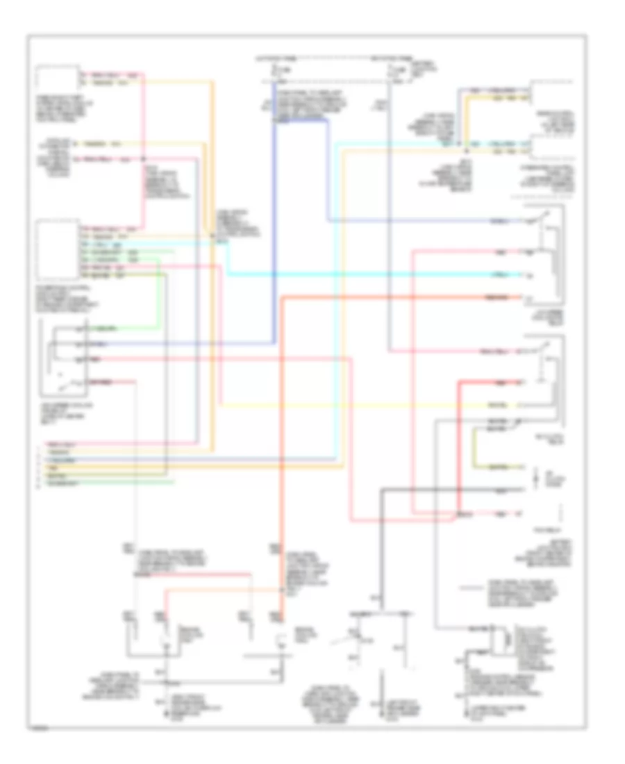
Automatic A/C Wiring Diagram (1 of 2) for Ford Taurus LX 1999

List of elements for Automatic A/C Wiring Diagram (1 of 2) for Ford Taurus LX 1999:
- (left front fender, near battery) g101
- (main wiring assembly, in breakout to passive anti-theft system (pats) module)
- (main wiring assembly, near breakout to passenger's airbag) s217
- 3.0l
- 3.4l sho
- 87a
- A/c clutch cycling pressure switch (right front of engine compartment, behind right headlamp)
- A/c high pressure switch (front center of engine compartment, left of power steering pump)
- Ambient temp
- Ambient temperature sensor (center of radiator grille)
- Battery
- Battery junction box (front center of engine compartment, behind radiator)
- Blend door actuator (below dash, on right side of a/c plenum)
- Blend dr act
- Blend dr act out
- Blend dr act pwr
- Blend dr act rtn
- Blower motor (right side of dash, below glove box on kick panel)
- Blower motor relay
- Blower motor speed controller (in right side of dash)
- Blower mtr out
- Blower rly ctrl
- C2043
- C215
- C225
- C235
- Center of kick panel) g103
- Cycling pres sw
- Data bus
- Engine control sensor harness, near breakout to fuel injector 6)
- Fuse 11 40a
- Fuse 13 5a
- Fuse 24 5a
- Fuse junction panel
- G200 (lower side of inner glove box frame)
- Ground
- Hot at all times
- Hot in run
- Ignition
- In car temp sens
- In-car temperature sensor (in vent tube near climate controls)
- Multi (+)
- Multi (-)
- Near breakout to passenger's airbag) s216
- Remote climate control (rcc) module (behind right side of dash, behind glove box)
- S156
- S215
- Signal return
- Solid state
- Sunload sensor
- Sunload sensor (in left front corner of dash near windshield)
- Tan
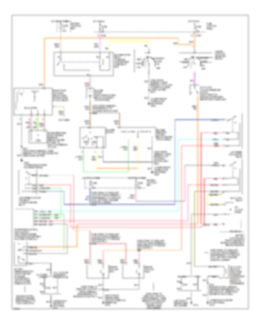
Automatic A/C Wiring Diagram (2 of 2) for Ford Taurus LX 1999
List of elements for Automatic A/C Wiring Diagram (2 of 2) for Ford Taurus LX 1999:
- (dash panel to headlamp junction wiring assembly, near breakout to engine cooling fan 1)
- (dash panel to headlamp junction wiring assembly, near breakout to ground g100 left front fender, near air cleaner)
- (dash panel to headlamp junction wiring assembly, near breakout to ground g100, left front fender near air cleaner)
- (dash panel to headlamp junction wiring assembly, near breakout to ground g100, left front fender near air cleaner) s132
- (left front fender near air cleaner) g104
- (main wiring assembly, in breakout to transmission control switch) s218
- (main wiring assembly, near breakout to left side of i/p fuse panel) s211
- (right front fender near coolant overflow reservoir) g105
- (upper right center of kick panel) g103
- 3.0l
- 3.4l sho
- A/c clutch diode
- A/c clutch field coil (right front of engine compartment, on front side of a/c compressor)
- A/c clutch relay
- Battery junction box
- Battery junction box (front center of engine compartment, behind radiator)
- Data link connector (partial) (mounted on dash, below steering column)
- Engine cooling fan 1
- Engine cooling fan 2
- Fuse 10a
- Fuse 40a
- High speed cooling fan relay (in relay center box 1)
- Hot at all times
- Integrated control panel (icp) (centered in dash, to right of steering column)
- Low speed cooling fan relay
- Passive anti-theft system (pats) module (in center of dash, behind integrated control panel)
- Pcm relay
- Powertrain control module (pcm) (right rear corner of engine compartment, mounted in firewall)
- Rear control unit (rcu) (in left rear of vehicle)
- Red
- S133
- S135
- S145
- S213 (main wiring assembly, near breakout to in-car temperature sensor)
- S219 (main wiring assembly, in breakout to transmission control switch)
- Tan
Manual A/C Wiring Diagram for Ford Taurus LX 1999
List of elements for Manual A/C Wiring Diagram for Ford Taurus LX 1999:
- (dash panel to headlamp junction wiring assembly, near breakout to engine cooling fan 1)
- (dash panel to headlamp junction wiring assembly, near breakout to engine cooling fan 1) s131
- (dash panel to headlamp junction wiring assembly, near breakout to engine cooling fan 1) s136
- (dash panel to headlamp junction wiring assembly, near breakout to ground g100 left front fender, near air cleaner)
- (dash panel to headlamp junction wiring assembly, near breakout to ground g100, left front fender near air cleaner)
- (dash panel to headlamp junction wiring assembly, near breakout to ground g100, left front fender near air cleaner) s132
- (left front fender near air cleaner)
- (lower side of inner glove box frame) g200
- (main wiring assembly, near breakout to glove box switch/lamp) s229
- (main wiring assembly, near breakout to glove box switch/lamp) s230
- (not used)
- (right front fender near coolant overflow reservoir) g105
- (upper right center of kick panel) g103
- 3.0l
- 3.0l (12-valve) 49 states & 3.0l (24-valve)
- 3.4l sho
- A/c clutch cycling pressure switch (right front of engine compartment, behind right headlamp)
- A/c clutch diode
- A/c clutch field coil (right side of engine compartment, on front side of a/c compressor)
- A/c clutch relay
- A/c high pressure switch (front center of engine compartment, left of power steering pump)
- Air temperature door variable resistor (behind center of dash, to right of steering column)
- All other models
- Battery junction box
- Battery junction box (front center of engine compartment, behind radiator)
- Blend door actuator (below dash, on right side of a/c plenum)
- Blower motor (right side of dash, below glove box on kick panel)
- Blower motor relay (in engine compartment fuse/relay box)
- Blower resistor (in dash, below center of glove box)
- Blower switch
- C225
- C235
- Center of kick panel) g103
- Def
- Engine control sensor harness, near breakout to fuel injector 6)
- Engine cooling fan 1
- Engine cooling fan 2
- Floor
- Floor/vent
- Fuse 10a
- Fuse 15a
- Fuse 40a
- Fuse 5a
- Fuse junction panel
- G104
- G200 (lower side of inner glove box frame)
- Heater function selector switch
- High speed cooling fan relay (in relay center box 1)
- Hot at all times
- Hot in run
- Low speed cooling fan relay
- Max
- Med hi
- Med lo
- Mix
- Norm
- Off
- Pcm relay
- Powertrain control module (pcm) (right rear corner, of engine compartment, mounted in firewall)
- Red
- S133
- S135
- S145
- S156
- S212 (main wiring assembly, near breakout to in-line connector, near cigar lighter)
- Solid state
- Vent