AIR CONDITIONING
3.8L
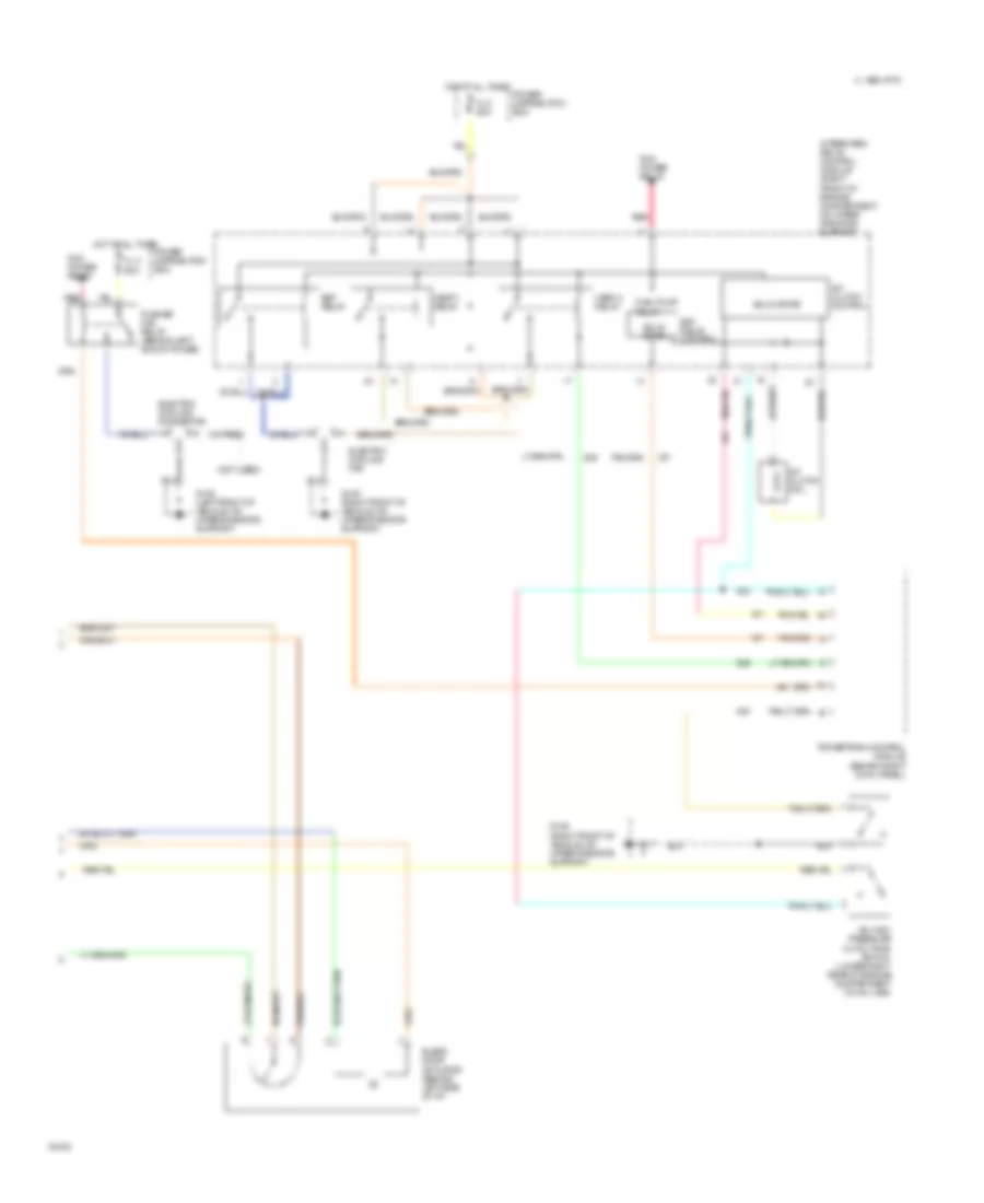
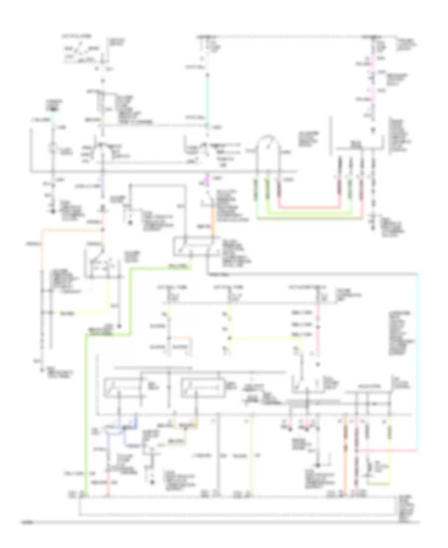
3.8L SC, A/C Wiring Diagram, Auto A/C (1 of 2) for Ford Thunderbird Super Coupe 1995

List of elements for 3.8L SC, A/C Wiring Diagram, Auto A/C (1 of 2) for Ford Thunderbird Super Coupe 1995:
- 2 std fuse 5a
- 30a
- A/c clutch cycling pressure switch (right rear of engine compartment on accumulator)
- A/c fuse 10a
- Acc
- Atc ambient temperature sensor (right front of vehicle, on lower radiator support)
- Blower in-line fuse holder (behind left side of i/p, taped to harness)
- Blower motor
- Blower motor speed controller (behind right side of i/p)
- C233
- C240
- C298
- Cold engine lockout switch (top right side of engine)
- Def
- Flr
- Flr/def
- G202 (behind i/p, right of steering column)
- G203 (behind right cowl panel)
- Hot at all times
- Hot in run
- Ignition switch
- In-car temperature sensor (behind top left side of i/p)
- Interior lights system
- Joint connec- tor 1
- Joint connector
- Lock
- Max
- Norm
- Off
- Off pan/flr
- Outside/ recirculate solenoid (behind right side of i/p)
- Pan/flr flr
- Panel
- Power distribution box
- Primary junction block
- Run
- Run fuse 5a
- Secondary junction block
- Semi-automatic temperature control module (center of i/p)
- Solid state
- Start
- Sunload sensor (behind right top of i/p)
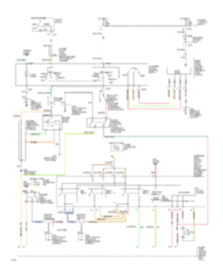
3.8L SC, A/C Wiring Diagram, Auto A/C (2 of 2) for Ford Thunderbird Super Coupe 1995
List of elements for 3.8L SC, A/C Wiring Diagram, Auto A/C (2 of 2) for Ford Thunderbird Super Coupe 1995:
- (not used)
- A/c clutch coil
- A/c clutch control
- A/c high pressure cutout/fan switch (lower right rear of engine compartment on a/c line)
- Blend door actuator (behind left side of i/p)
- C 1995 vftc
- Edf relay
- Edf relay control
- Electric cooling fan
- Electric cooling pusher fan
- Fl 5 60a
- Fuel pump relay
- G109 (left front of vehicle, on upper radiator support)
- G109 (right front of vehicle, on upper radiator support)
- Hedf 1 relay
- Hedf 2 relay
- Hot at all times
- Integrated relay control module (right front of engine compartment on upper radiator support
- Pcm power relay
- Power distribution box
- Powertrain control module (behind right cowl panel)
- Pusher fan relay (behind left shock tower)
- Red
- Solid state
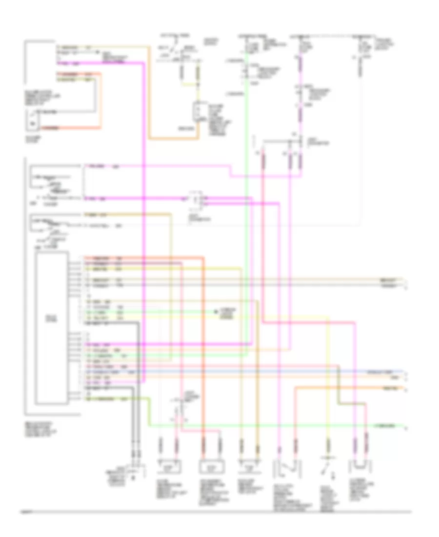
3.8L SC, A/C Wiring Diagram, Manual A/C for Ford Thunderbird Super Coupe 1995
List of elements for 3.8L SC, A/C Wiring Diagram, Manual A/C for Ford Thunderbird Super Coupe 1995:
- (behind right
- (not used)
- 30a
- A/c clutch coil
- A/c clutch control
- A/c clutch cycling pressure switch (right rear of engine compartment on accumulator)
- A/c fuse 10a
- A/c high pressure cutout/fan switch (lower right rear of engine on a/c line)
- A/c-heater fuction selector switch
- Acc
- Blend door motor control (behind center of i/p, on plenum)
- Blower in-line fuse holder (behind left side of i/p, taped to harness)
- Blower motor
- Blower motor switch
- Blower resistors (behind right side of i/p, in plenum)
- C2001
- C2003
- C211
- C232
- C233
- C263
- Cold
- Cowl panel)
- Def
- Def/flr
- Edf relay
- Edf relay control
- Electric cooling fan
- Electric cooling pusher fan
- Fl 5 60a
- Flr
- Fuel pump relay
- G108 (left front of vehicle, on upper radiator support)
- G109 (right front of vehicle, on upper radiator support)
- G202 (behind i/p, right side of steering column)
- G203
- G203 (behind right cowl panel)
- Hedf 1 relay
- Hedf 2 relay
- Hot at all times
- Hot in run
- Ignition switch
- Illumi- nation
- Integrated relay control module (right front of engine compartment on upper radiator support
- Interior lights system
- Lock
- Max
- Nca
- Norm
- Off
- Pan/flr
- Panel
- Pcm power relay
- Power distribution box
- Power- train control module (behind right cowl)
- Primary junction block
- Pusher fan relay (behind left shock tower)
- Red
- Run
- Run fuse 10a
- Secondary junction block
- Solid state
- Start
- Warm
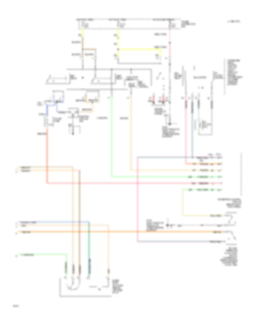
3.8L, A/C Wiring Diagram, Auto A/C (1 of 2) for Ford Thunderbird Super Coupe 1995
List of elements for 3.8L, A/C Wiring Diagram, Auto A/C (1 of 2) for Ford Thunderbird Super Coupe 1995:
- 2 std fuse 5a
- 30a
- A/c clutch cycling pressure switch (right rear of engine compartment on accumulator)
- A/c fuse 10a
- Acc
- Atc ambient temperature sensor (right front of vehicle, on lower radiator support)
- Blower in-line fuse holder (behind left side of i/p, taped to harness)
- Blower motor
- Blower motor speed controller (behind right side of i/p)
- C232
- C233
- C240
- C298
- Cold engine lockout switch (top right side of engine)
- Def
- Flr
- Flr/def
- G202 (behind i/p, right of steering column)
- G203 (behind right cowl panel)
- Hot at all times
- Hot in run
- Ignition switch
- In-car temperature sensor (behind top left side of i/p)
- Interior lights system
- Joint connec- tor 1
- Joint connector
- Lock
- Max
- Norm
- Off
- Off pan/flr
- Outside/ recirculate solenoid (behind right side of i/p)
- Pan/flr flr
- Panel
- Power distribution box
- Primary junction block
- Run
- Run fuse 5a
- Secondary junction block
- Semi-automatic temperature control module (center of i/p)
- Solid state
- Start
- Sunload sensor (behind right top of i/p)
3.8L, A/C Wiring Diagram, Auto A/C (2 of 2) for Ford Thunderbird Super Coupe 1995
List of elements for 3.8L, A/C Wiring Diagram, Auto A/C (2 of 2) for Ford Thunderbird Super Coupe 1995:
- (3.8l)
- (4.6l)
- 10a
- 4.6l only
- A/c clutch coil
- A/c clutch control
- A/c high pressure cutout/fan switch (lower right rear of engine compartment on a/c line)
- Blend door actuator (behind left side of i/p)
- C 1995 vftc
- Edf relay
- Edf relay control
- Electric cooling fan
- Engine controls system
- Fl 15 20a
- Fl 3 20a
- Fl 5 60a
- Fuel pump relay
- G109 (right front of vehicle, on upper radiator support)
- Hedf relay
- Hot at all times
- Hot in start or run
- In-line fuse
- Integrated relay control module (right front of engine compartment on upper radiator support
- Pcm power relay
- Power distribution box
- Powertrain control module (behind right cowl panel)
- Red
- Solid state
3.8L, A/C Wiring Diagram, Manual A/C for Ford Thunderbird Super Coupe 1995
List of elements for 3.8L, A/C Wiring Diagram, Manual A/C for Ford Thunderbird Super Coupe 1995:
- (3.8l) (4.6l)
- (behind right
- 10a
- 30a
- 4.6l only
- A/c clutch coil
- A/c clutch control
- A/c clutch cycling pressure switch (right rear of engine compartment on accumulator)
- A/c fuse 10a
- A/c high pressure cutout/fan switch (lower right rear of engine on a/c line)
- A/c-heater fuction selector switch
- Acc
- Blend door motor control (behind center of i/p, on plenum)
- Blower in-line fuse holder (behind left side of i/p, taped to harness)
- Blower motor
- Blower motor switch
- Blower resistors (behind right side of i/p, in plenum)
- C2001
- C2003
- C211
- C232
- C233
- C263
- Cold
- Cowl panel)
- Def
- Def/flr
- Edf relay
- Edf relay control
- Electric cooling fan
- Engine controls system
- Fl 15 20a
- Fl 3 20a
- Fl 5 60a
- Flr
- Fuel pump relay
- G109 (right front of vehicle, on upper radiator support)
- G202 (behind i/p, right side of steering column)
- G203
- G203 (behind right cowl panel)
- Hedf relay
- Hot at all times
- Hot in run
- Hot in start or run
- Ignition switch
- Illumi- nation
- In-line fuse (in engine harness)
- Integrated relay control module (right front of engine compartment on upper radiator support
- Interior lights system
- Lock
- Max
- Nca
- Norm
- Off
- Pan/flr
- Panel
- Pcm power relay
- Power distribution box
- Power- train control module (behind right cowl)
- Primary junction block
- Red
- Run
- Run fuse 10a
- Secondary junction block
- Solid state
- Start
- Warm
4.6L
4.6L, A/C Wiring Diagram, Auto A/C (1 of 2) for Ford Thunderbird Super Coupe 1995
List of elements for 4.6L, A/C Wiring Diagram, Auto A/C (1 of 2) for Ford Thunderbird Super Coupe 1995:
- 2 std fuse 5a
- 30a
- A/c clutch cycling pressure switch (right rear of engine compartment on accumulator)
- A/c fuse 10a
- Acc
- Atc ambient temperature sensor (right front of vehicle, on lower radiator support)
- Blower in-line fuse holder (behind left side of i/p, taped to harness)
- Blower motor
- Blower motor speed controller (behind right side of i/p)
- C232
- C233
- C240
- C298
- Cold engine lockout switch (top right side of engine)
- Def
- Flr
- Flr/def
- G202 (behind i/p, right of steering column)
- G203 (behind right cowl panel)
- Hot at all times
- Hot in run
- Ignition switch
- In-car temperature sensor (behind top left side of i/p)
- Interior lights system
- Joint connec- tor 1
- Joint connector
- Lock
- Max
- Norm
- Off
- Off pan/flr
- Outside/ recirculate solenoid (behind right side of i/p)
- Pan/flr flr
- Panel
- Power distribution box
- Primary junction block
- Run
- Run fuse 5a
- Secondary junction block
- Semi-automatic temperature control module (center of i/p)
- Solid state
- Start
- Sunload sensor (behind right top of i/p)
4.6L, A/C Wiring Diagram, Auto A/C (2 of 2) for Ford Thunderbird Super Coupe 1995
List of elements for 4.6L, A/C Wiring Diagram, Auto A/C (2 of 2) for Ford Thunderbird Super Coupe 1995:
- (3.8l)
- (4.6l)
- 10a
- 4.6l only
- A/c clutch coil
- A/c clutch control
- A/c high pressure cutout/fan switch (lower right rear of engine compartment on a/c line)
- Blend door actuator (behind left side of i/p)
- C 1995 vftc
- Edf relay
- Edf relay control
- Electric cooling fan
- Engine controls system
- Fl 15 20a
- Fl 3 20a
- Fl 5 60a
- Fuel pump relay
- G109 (right front of vehicle, on upper radiator support)
- Hedf relay
- Hot at all times
- Hot in start or run
- In-line fuse
- Integrated relay control module (right front of engine compartment on upper radiator support
- Pcm power relay
- Power distribution box
- Powertrain control module (behind right cowl panel)
- Red
- Solid state
4.6L, A/C Wiring Diagram, Manual A/C for Ford Thunderbird Super Coupe 1995
List of elements for 4.6L, A/C Wiring Diagram, Manual A/C for Ford Thunderbird Super Coupe 1995:
- (3.8l) (4.6l)
- (behind right
- 10a
- 30a
- 4.6l only
- A/c clutch coil
- A/c clutch control
- A/c clutch cycling pressure switch (right rear of engine compartment on accumulator)
- A/c fuse 10a
- A/c high pressure cutout/fan switch (lower right rear of engine on a/c line)
- A/c-heater fuction selector switch
- Acc
- Blend door motor control (behind center of i/p, on plenum)
- Blower in-line fuse holder (behind left side of i/p, taped to harness)
- Blower motor
- Blower motor switch
- Blower resistors (behind right side of i/p, in plenum)
- C2001
- C2003
- C211
- C232
- C233
- C263
- Cold
- Cowl panel)
- Def
- Def/flr
- Edf relay
- Edf relay control
- Electric cooling fan
- Engine controls system
- Fl 15 20a
- Fl 3 20a
- Fl 5 60a
- Flr
- Fuel pump relay
- G109 (right front of vehicle, on upper radiator support)
- G202 (behind i/p, right side of steering column)
- G203
- G203 (behind right cowl panel)
- Hedf relay
- Hot at all times
- Hot in run
- Hot in start or run
- Ignition switch
- Illumi- nation
- In-line fuse (in engine harness)
- Integrated relay control module (right front of engine compartment on upper radiator support
- Interior lights system
- Lock
- Max
- Nca
- Norm
- Off
- Pan/flr
- Panel
- Pcm power relay
- Power distribution box
- Power- train control module (behind right cowl)
- Primary junction block
- Red
- Run
- Run fuse 10a
- Secondary junction block
- Solid state
- Start
- Warm