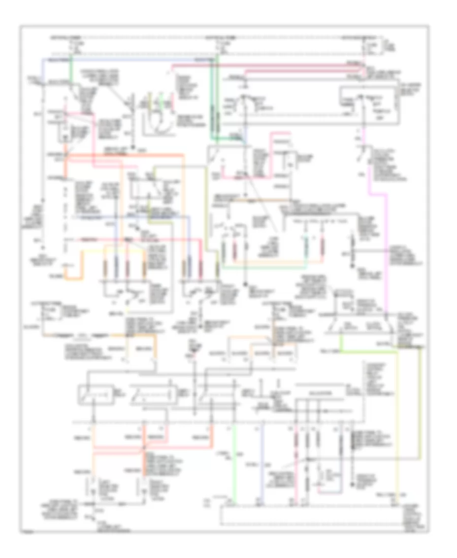
AIR CONDITIONING
Air Conditioning Wiring Diagrams for Ford Windstar 1997
List of elements for Air Conditioning Wiring Diagrams for Ford Windstar 1997:
- (a/c blower motor harn, in aux blwr motor breakout)
- (a/c blwr mtr harn, in left "b" pillar)
- (a/c blwr mtr harn, near aux mtr blwr res ass'y breakout)
- (behind left
- (behind left cowl panel)
- (behind right side of i/p)
- (behind right side of i/p) g201
- (dash panel to headlamp junction harn, near left elect cooling fan motor breakout)
- (dash panel to headlamp junction harn, near left headlamp breakout) s105
- (dash panel to headlamp junction harn, near left headlamp breakout) s135
- (eng control sens harn, in a/c clutch coil breakout)
- (engine harn, left rear of eng compt (3.8l) (engine harn, right rear of eng compt) (3.0l)
- (front of transaxle on stud) g130
- (main harn, near inst cluster breakout)
- (window regulator jumper harn, near blower motor breakout)
- 3.0l
- 3.8l
- A/c clutch coil
- A/c clutch control
- A/c clutch cycling pressure switch (right rear of engine compartment on accumulator)
- A/c high pressure cutout/ fan switch (lower right rear of engine compartment)
- A/c-heater
- Aux ctrl
- Auxiliary a/c relay (left of rear seat)
- Auxiliary blower motor
- Auxiliary blower motor relay (in i/p fuse panel)
- Auxiliary blower motor resistor assembly (behind panel, left of rear seat)
- B 60a
- Blend door actuator (behind right side of i/p)
- Blower motor
- Blower motor resistor (behind right side of i/p)
- Blower motor switch
- Clutch switch
- Constant control relay module (left front of engine compartment)
- Cooling fan dropping resistor (lower right front of engine compartment)
- Cowl panel)
- Def
- Def/flr
- Edf relay
- Edf relay control
- Engine compartment fuse box
- Fan switch
- Flr
- Front auxiliary blower motor switch
- Front blower motor relay (in i/p fuse panel)
- Fuel pump relay
- Fuse
- Fuse 10a
- Fuse 30a
- G100 (lower left front of engine)
- G200
- G201
- G201 (behind right side of i/p)
- G308 (on left "b" pillar)
- H 40a
- Hedf 1 relay
- Hedf 2 relay
- Hot at all times
- Hot in acc or run
- I/p fuse panel
- Left electric cooling fan motor
- Max
- Nca
- Norm
- Off
- Pan/flr
- Panel
- Pcm power relay
- Power- train control module (behind right side of i/p)
- Rear auxiliary blower motor switch
- Red
- Red/pnk
- Right electric cooling fan motor
- S102
- S112 (3.8l) s113 (3.0l)
- S134 (dash panel to headlamp junction harn, near left elect cooling fan motor breakout)
- S137
- S202 (main harn, behind right side of i/p)
- S205
- S205 (main harn, near inst cluster breakout)
- S212
- S218 (main harn, behind left side of i/p)
- S267 (window regulator jumper harn, in blower motor resistor breakout)
- S302
- S314
- S315
- S316
- S317
- Selector switch
- Solid state
- Temperature control potentiometer
 English