AIR CONDITIONING
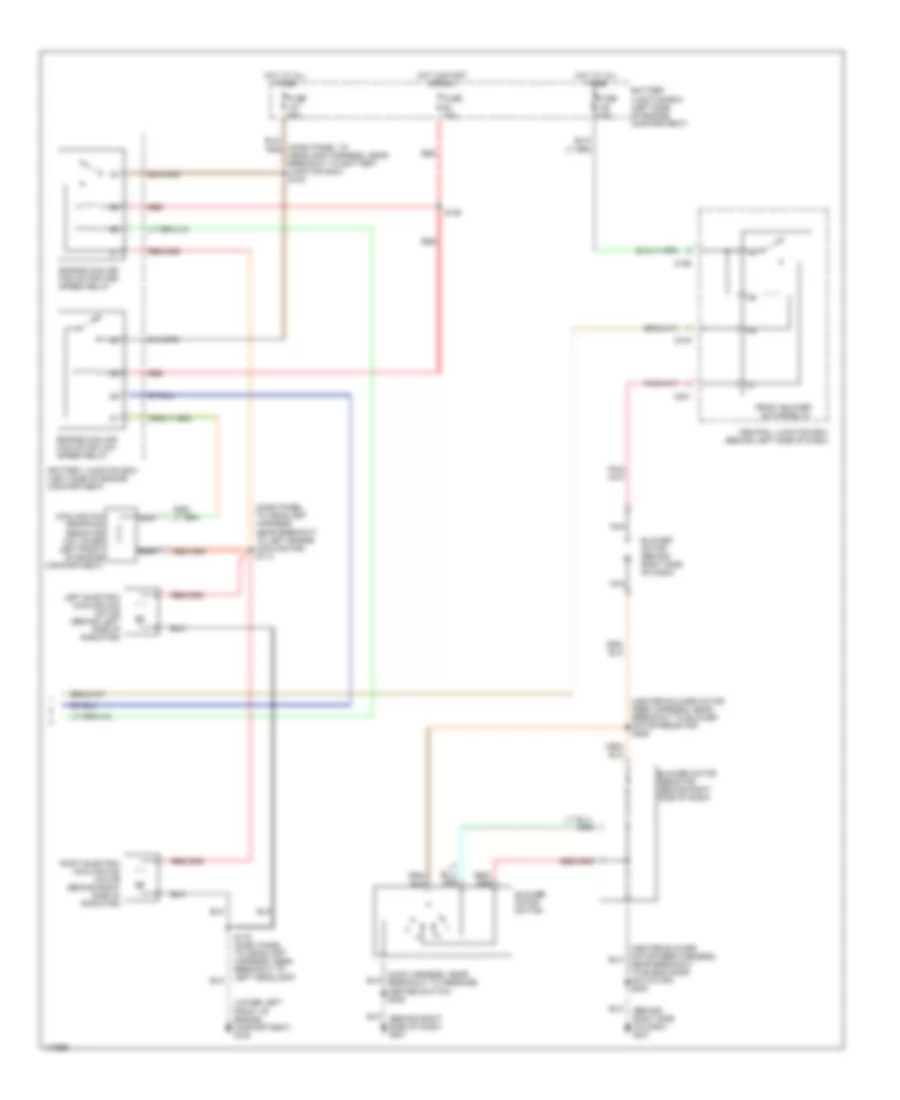
Manual A/C Wiring Diagram (1 of 2) for Ford Windstar SE 2001

List of elements for Manual A/C Wiring Diagram (1 of 2) for Ford Windstar SE 2001:
- (behind right side of dash) g201
- (dash panel to headlamp harness, near breakout 42 pin in-line connector, left rear of engine compartment)
- (dash panel to headlamp harness, near breakout to 42 pin in-line connector, left rear of engine compartment)
- (heater blower motor feed harness near breakout to blend door actuator) s230
- (lower left front of engine compartnment) g100
- (main harness, near breakout to 16 pin in-line connector, under left side of dash) s219
- (main harness, near breakout to instrument cluster connector c239)
- (main harness, near breakout to message center switch) s212
- A/c clutch cycling pressure switch (in right front of engine compartment on a/c accumulator)
- A/c clutch cycling sw
- A/c clutch field coil
- A/c clutch relay
- A/c clutch relay ctrl
- A/c demand switch
- A/c high press cutout sw
- A/c high pressure cutout/fan switch (center front of engine compartment)
- A/c indicator
- A/c switch
- A/c-heater control switch
- Auxiliary blower sense
- Auxiliary blower speed
- Battery junction box (left side of engine compartment)
- Blend door actuator (behind right side of dash)
- Blower switch
- C195
- C202
- C239
- C240
- C241
- C346
- Central junction box (behind left side of dash)
- Climate control switch assembly
- Def
- Driver's temperature
- Floor
- Front a/c ctrl sig
- Front blower motor relay output
- Front electronic module (fem) (below left side of dash)
- Fuse 10 15a
- Fuse 10a
- Fuse 15a
- Gnd
- High speed fan ctrl
- Hot at all times
- Hot in run
- Hot in start or run
- Ignition
- Illumination (x5)
- Instrument cluster
- Interior lights system
- Low speed fan ctrl
- Main lt & a/c mode sw rtn
- Max
- Mix
- Nca
- Norm
- Off
- Ohms
- Panel/floor
- Pnk
- Powertrain control module (pcm) (behind right side of dash, through firewall)
- Rear blend door sense
- Rear defrost switch
- Rear temperature
- Rear wdo defrost (on) ind
- Rear window defrost switch
- Ref volt
- S115 (dash panel to headlamp harness, near breakout to left headlamp)
- S117
- S131
- S133
- Signal return
- Switch signal return
- Vent
- W/auxiliary air conditioning
Manual A/C Wiring Diagram (2 of 2) for Ford Windstar SE 2001
List of elements for Manual A/C Wiring Diagram (2 of 2) for Ford Windstar SE 2001:
- (behind right side of dash) g201
- (dash panel to headlamp harness, near breakout to battery junction box) s123
- (dash panel to headlamp harness, near breakout to left engine cooling fan) s113
- (heater blower motor feed harness, near breakout to blower motor resistor) s229
- (lower left front of engine compartment) g100
- Battery junction box (left side of engine compartment)
- Blower motor (behind right side of dash)
- Blower motor resistor (behind right side of dash)
- Blower motor switch
- C195
- C201
- C219
- Central junction box (behind left side of dash)
- Cooling fan dropping resistor (on lower left front of engine compartment)
- Engine cooling fan motor high speed relay
- Engine cooling fan motor low speed relay
- Front blower motor relay
- Fuse 15a
- Fuse 40a
- Fuse 50a
- Hot at all times
- Hot in start or run
- Left electric cooling fan motor (behind left side of radiator)
- Nca
- Near breakout to blend door actuator) s230
- Red
- Right electric cooling fan motor (behind right side of radiator)
- S116 (dash panel to headlamp harness, near breakout to left headlamp)
- S125
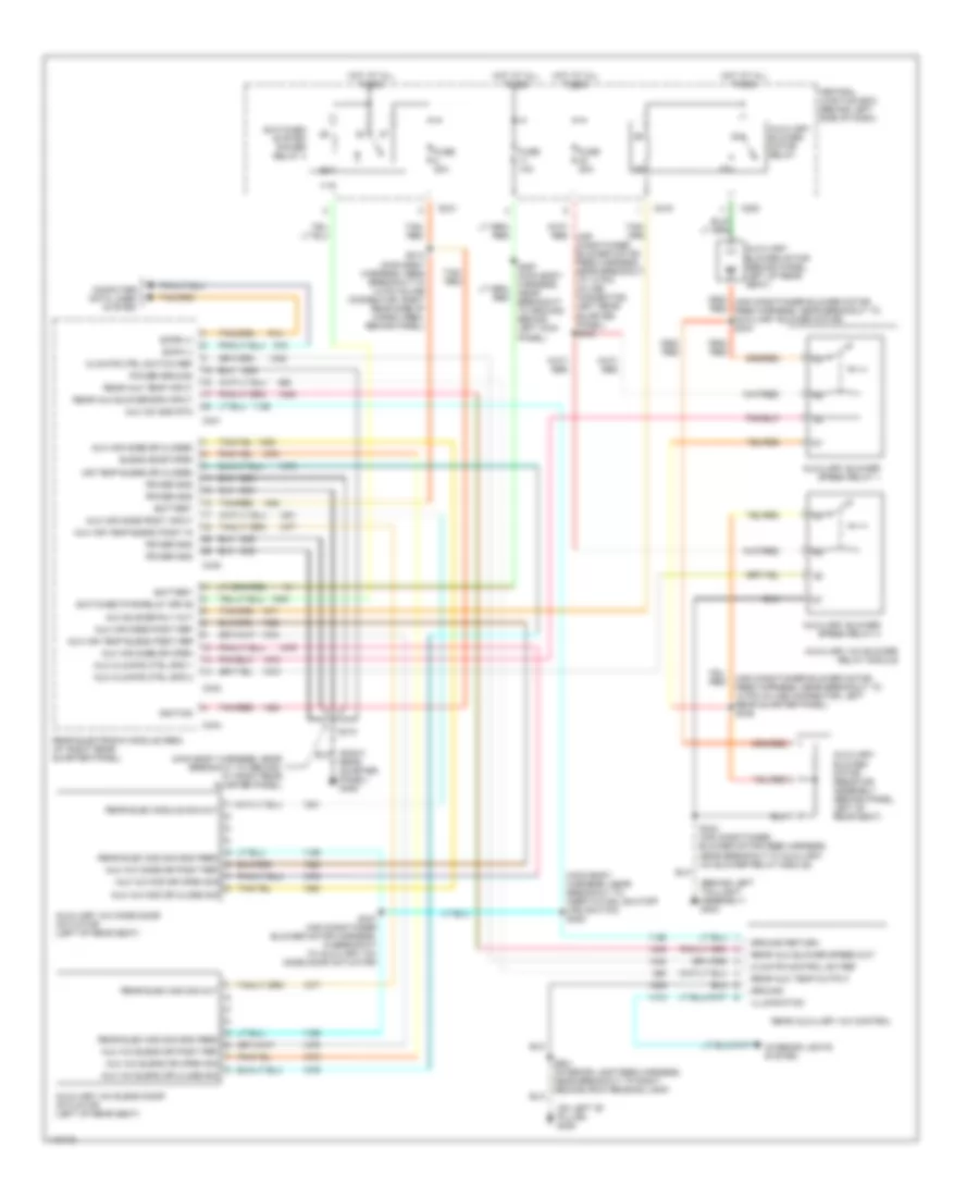
Manual A/C Wiring Diagram, Rear A/C for Ford Windstar SE 2001
List of elements for Manual A/C Wiring Diagram, Rear A/C for Ford Windstar SE 2001:
- (air conditioner blower motor feed harness, near breakout to 12 pin in-line connector, left rear quarter panel) s346
- (behind left taillight assembly) g404
- (main body harness, near breakout to ground, at right rear quarter panel)
- (main body harness, near breakout to inertia fuel shutoff (ifs) switch) s308
- (on left "b" pillar) g308
- Air temp blend dr closed
- Aux a/c blend dr close sig
- Aux a/c blend dr open sig
- Aux a/c blend dr posit ref
- Aux a/c gnd rtn
- Aux a/c mod dr close sig
- Aux a/c mod dr open sig
- Aux a/c mode dr posit ref
- Aux air mode dr closed
- Aux air mode dr open
- Aux air mode posit input
- Aux air mode posit ref
- Aux air temp blend posit in
- Aux air temp blend posit ref
- Aux blower rly out
- Aux climate ctrl spd 1
- Aux climate ctrl spd 2
- Auxiliary a/c blend door actuator (left of rear seat)
- Auxiliary a/c blower relay module
- Auxiliary a/c mode door actuator (left of rear seat)
- Auxiliary blower motor (behind panel, left of rear seat)
- Auxiliary blower motor relay
- Auxiliary blower motor resistor assembly (behind panel, left of rear seat)
- Auxiliary blower speed relay 1
- Auxiliary blower speed relay 2
- Battery
- Blend door open
- C219
- C220
- C221
- C341
- C342
- C343
- C344
- Central junction box (behind left side of dash)
- Climate control sw ref
- Climate ctrl switch ref
- Computer data lines system
- Fuse 10a
- Fuse 20a
- Ground
- Ground return
- Hot at all times
- Ignition
- Illumination
- Interior lights system
- Power gnd
- Power ground
- Rear aux blower spd input
- Rear aux blower speed out
- Rear aux temp input
- Rear aux temp output
- Rear auxiliary a/c control
- Rear elec mod sig gnd feed
- Rear elec mod sig out
- Rear elec module sig out
- Rear electronic module (rem) (at right rear quarter panel)
- Rear quarter panel) g405
- Red
- S310
- S313 (main body harness, near breakout to 14 pin in-line connector, right rear side of cargo area, behind panel)
- S343 (air conditioner blower motor feed harness, near breakout to auxiliary a/c blower relay module)
- S347 (air conditioner blower motor harness, in breakout to auxiliary a/c mode door actuator)
- S367 (main body harness, near breakout to ground behind left kick panel)
- S901 (interior lamp feed harness, near breakout to right second row reading lamp)
- Scpa (-)
- Scpb (+)
- Switched pwr relay drive
- Switched system power relay 4
- Tan/ red
- Tan/red