AIR CONDITIONING
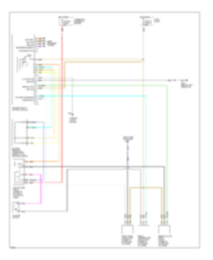
A/C Wiring Diagram for GMC Cab & Chassis C3500 1996

List of elements for A/C Wiring Diagram for GMC Cab & Chassis C3500 1996:
- (7.4l vin j)
- (left rear of engine compt)
- (rear of compressor)
- (right side
- (right side of engine)
- (right side of i/p)
- A/c comp mini fuse 10a
- A/c compressor clutch
- A/c compressor clutch cycling switch (in low pressure line near compressor)
- A/c compressor clutch relay (in underhood fuse/relay center)
- A/c ctrl
- A/c disable
- A/c high pressure cutout switch (at a/c compressor)
- A/c maxi fuse 3 50a
- A/c req
- A/c switch
- Above starter motor)
- Air temp dr sensor
- Aux fan ctrl
- Aux fan mini fuse 30a
- Auxiliary cooling fan a/c pressure switch
- Auxiliary cooling fan motor
- Auxiliary cooling fan relay (7.4l vin j) (in underhood fuse/relay center)
- Auxiliary cooling fan temperature switch (right cylinder head
- Battery
- Blower motor
- Blower resistor (under right side of i/p, on heater housing)
- Blower switch
- C10
- Center
- Defogger element
- Diesel
- Diode
- Front mode door motor (under i/p on heater- a/c case)
- Front temperature door motor (under i/p on heater- a/c case)
- Fuse block
- G101 (right inner fender, near battery)
- G120
- G202 (behind left side of i/p)
- Gas
- Ground
- Heater and a/c control module
- High blower relay (under i/p on top of heater-a/c case)
- Hot at all times
- Hot in run
- Hot in run bulb test or start
- Hot in run or start
- Htr a/c fuse 12 25a
- Ign e mini fuse 10a
- Ign mini fuse 10a
- Ignition
- Illumination
- Interior lights system
- Mode signal
- Nca
- Of engine)
- Off
- Pnk
- Powertrain control module (diesel) vehicle control module (gas)
- Rear defogger system
- Recirculation door motor (under i/p on heater- a/c case)
- Red
- Tan
- Underhood fuse-relay
- Underhood fuse-relay center
- Valve ctrl
- Water valve (suburban, utility, crew cab only) (right center of intake area)
Heater Wiring Diagram for GMC Cab & Chassis C3500 1996
List of elements for Heater Wiring Diagram for GMC Cab & Chassis C3500 1996:
- (right side of engine)
- A/c maxi fuse 3 50a
- Air temp dr sensor
- Battery
- Blower motor
- Blower resistor (under right side of i/p, on heater housing)
- Blower switch
- C10
- Defogger element
- Front mode door motor (under i/p on heater- a/c case)
- Front temperature door motor (under i/p on heater- a/c case)
- Fuse block
- G120
- G202 (behind left side of i/p)
- Ground
- Heater and a/c control module
- High blower relay (under i/p on top of heater-a/c case)
- Hot in run
- Htr a/c fuse 12 25a
- Ignition
- Illumination
- Interior lights system
- Mode signal
- Off
- Rear defogger system
- Recirc ctrl
- Recirculation door motor (under i/p on heater- a/c case)
- Red
- Tan
- Underhood fuse-relay center