AIR CONDITIONING
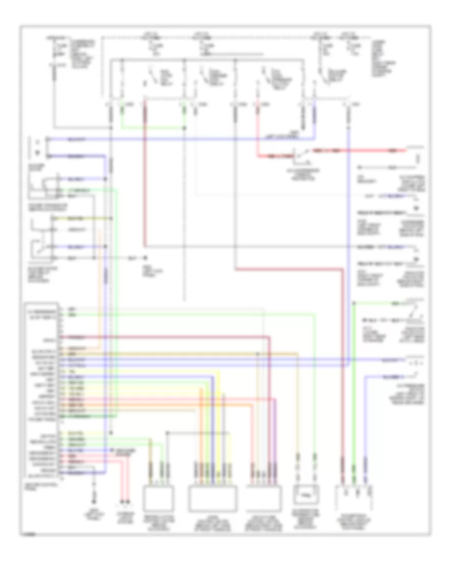
Manual A/C Wiring Diagram for Honda CR-V EX 1999
List of elements for Manual A/C Wiring Diagram for Honda CR-V EX 1999:
- (on bracket)
- 5v reference
- A/c com- pressor clutch relay
- A/c compres- sor clutch (lower left front of eng)
- A/c compressor thermal protector
- A/c on out
- A/c pressure switch (left front of engine compt, on receiver drier)
- A17
- A20
- A27
- Acc
- Acs
- Air mix
- Air mix cool
- Air mix hot
- Air mixture control motor (behind right side of front console)
- Battery
- Blower motor
- Blower motor high relay (behind glove box)
- Blower motor relay
- Blwr mtr ctl
- Blwr mtr hi
- C351
- C352
- C353
- C418
- Con- denser fan relay
- Condenser fan motor (behind left side of rad)
- Defogger sw
- Defogger system
- Defrost
- Dimming ckt
- Evap temp in
- Evaporator temperature sensor (behind glove box)
- Fanc
- Fresh
- Fuse 20a
- Fuse 40a
- Fuse 7.5a
- G100 (left front corner of eng compt)
- G101 (right front corner of eng compt)
- G117 (lower right rear of engine)
- G200 (left kick panel)
- Ground
- Heat
- Heat/defrst
- Heat/vent
- Heater control panel
- Hot at all times
- Hot in on
- Ignition
- Interior lights system
- Mode control motor (behind left side of front console)
- Motor gnd
- Power trans
- Power transistor (behind glove box)
- Powertrain control module (behind right kick panel)
- Rad- iator fan relay
- Radiator fan motor (behind right side of rad)
- Radiator fan switch (left rear of cyl head)
- Recirculate
- Recirculation control motor (behind glove box)
- Red
- Sensor gnd
- Under- hood fuse/ relay box (right rear corner of engine compt)
- Underdash fuse/relay box (behind dash, left of strng column)
- Vent
 English