AIR CONDITIONING
Automatic A/C Wiring Diagram (1 of 2) for Honda CR-V EX 2008

List of elements for Automatic A/C Wiring Diagram (1 of 2) for Honda CR-V EX 2008:
- (lower left front of engine) a/c compressor
- (under left side of dash) under-dash junction box
- (under middle of dash) g503
- A/c compressor clutch
- A/c compressor clutch relay
- A12
- A13
- Acs
- Amd- p
- Amd-p
- B-can
- B11
- B12
- B13
- Blower feedback
- Blw-g
- Blw-v
- Climate control unit
- Computer data lines system
- Driver's air mix control motor (under left side of dash, on hvac unit)
- Evaporator temperature sensor (under middle of dash)
- F/r d-p
- F20
- F26
- Front passenger's air mix control motor (under left side of dash, on hvac unit)
- Frs
- Fuse 10a
- Fuse 7.5a
- G12
- Gnd
- Hot at all times
- Hot in on
- Ig2
- Ig2 hav
- Ill-
- In-car temperature sensor (in left side of dash)
- Interior lights
- Junction connector c101 (left rear of engine compt)
- M- cool
- M- def
- M- hot
- M- vent
- M-cool
- M-frs
- M-hot
- M-rec
- M-vent
- Micu
- Mode
- Mode 1
- Mode 2
- Mode 3
- Mode 4
- Mode control motor (behind right side of dash, on hvac unit)
- Mode def
- N11
- Navigation system
- Nca
- Outside air temperature sensor (behind middle of front bumper)
- Pnk
- Rec
- Recirculation control motor (behind right side of dash, on blower unit)
- Red
- Red-p
- S5v
- Sens gnd
- Sens-com
- Small
- Sunlight sensor (top center of dash)
- System
- Tam
- Teva
- Thermal protector
- To blower motor relay (diagram 2 of 2)
- Tsun
- Under-dash fuse/relay box (under left side of dash)
- Under-hood fuse/relay box (on left side of engine compt)
- Usa: ex-l & canada
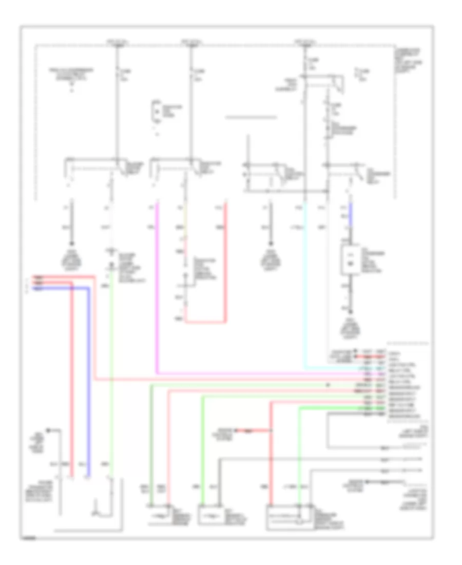
Automatic A/C Wiring Diagram (2 of 2) for Honda CR-V EX 2008
List of elements for Automatic A/C Wiring Diagram (2 of 2) for Honda CR-V EX 2008:
- A/c condenser fan diode
- A/c condenser fan motor (behind radiator)
- A/c condenser fan relay
- A/c pressure sensor (right side of engine compt)
- A14
- A16
- A19
- A21
- A33
- A36
- A37
- B23
- B33
- Blower motor (under right side of dash, on a/c blower unit)
- Blower motor relay
- Can-h
- Can-l
- Computer data lines system
- Ect sensor 1 (rear of engine)
- Ect sensor 2 (bottom of radiator)
- Engine controls system
- F11
- F12
- F14
- F16
- Fan control relay
- From a/c compressor clutch relay (diagram 1 of 2)
- Fuse 15a
- Fuse 20a
- Fuse 40a
- Fuse 7.5a
- G301 (under left side of engine compt)
- G302 (under left side of engine compt)
- G401 (under left side of dash)
- High fan ctrl
- Hot at all times
- Junction connector c404 (under left side of dash)
- Low fan ctrl
- Nca
- Pcm (left side of engine compt)
- Pgm-fi main sub-relay
- Power transistor (behind right side of dash, on hvac unit)
- Radiator fan diode
- Radiator fan motor (behind radiator)
- Radiator fan relay
- Red
- Ref voltage
- Relay ctrl
- Sensor ground
- Sensor input
- Under-hood fuse/relay box (on left side of engine compt)
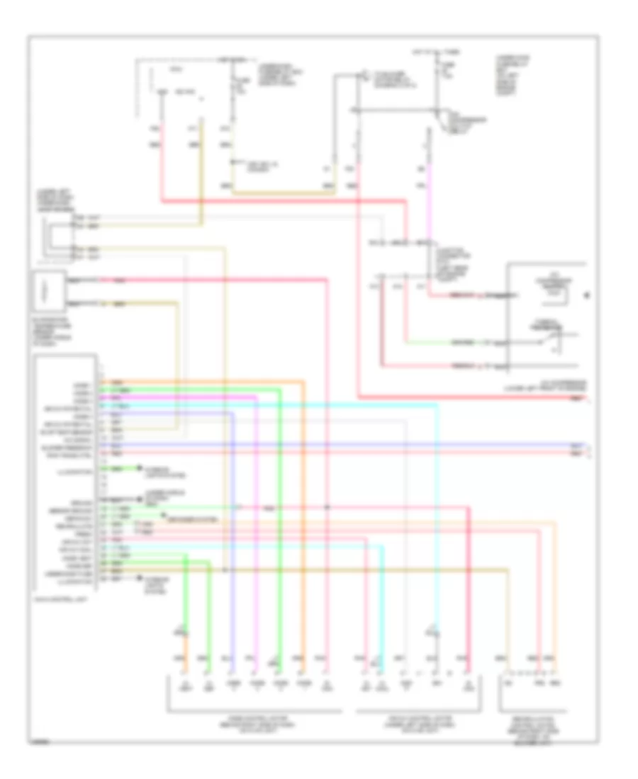
Manual A/C Wiring Diagram (1 of 2) for Honda CR-V EX 2008
List of elements for Manual A/C Wiring Diagram (1 of 2) for Honda CR-V EX 2008:
- (under left side of dash) under-dash junction box
- (under middle of dash) g503
- A/c compressor (lower left front of engine)
- A/c compressor clutch
- A/c compressor clutch relay
- A/c signal
- A11
- A12
- A13
- Acs
- Air mix control motor (under left side of dash, on hvac unit)
- Air mix cool
- Air mix hot
- Air mix potential
- Amd- p
- B11
- B12
- B13
- Blower feedback
- Defog sw
- Defogger system
- Evap temp sensor
- Evaporator temperature sensor (under middle of dash)
- F20
- F26
- Fresh
- Frs
- Fuse 10a
- Fuse 7.5a
- G12
- Ground
- Havc control unit
- Hot at all times
- Hot in on
- Ig2
- Ig2 hac
- Illumination
- Interior lights system
- Junction connector c101 (left rear of engine compt)
- M- cool
- M- def
- M- hot
- M- vent
- Micu
- Mode
- Mode 1
- Mode 2
- Mode 3
- Mode 4
- Mode control motor (behind right side of dash, on hvac unit)
- Mode def
- Mode vent
- N11
- Nca
- Pnk
- Pwr trans ctrl
- Rec
- Recirculate
- Recirculation control motor (behind right side of dash, on blower unit)
- Red
- S- com
- S5v
- Sensor ground
- Thermal protector
- To blower motor relay (diagram 2 of 2)
- Under-dash fuse
- Under-dash fuse/relay box (under left side of dash)
- Under-hood fuse/relay box (on left side of engine compt)
- Usa: ex-l & canada
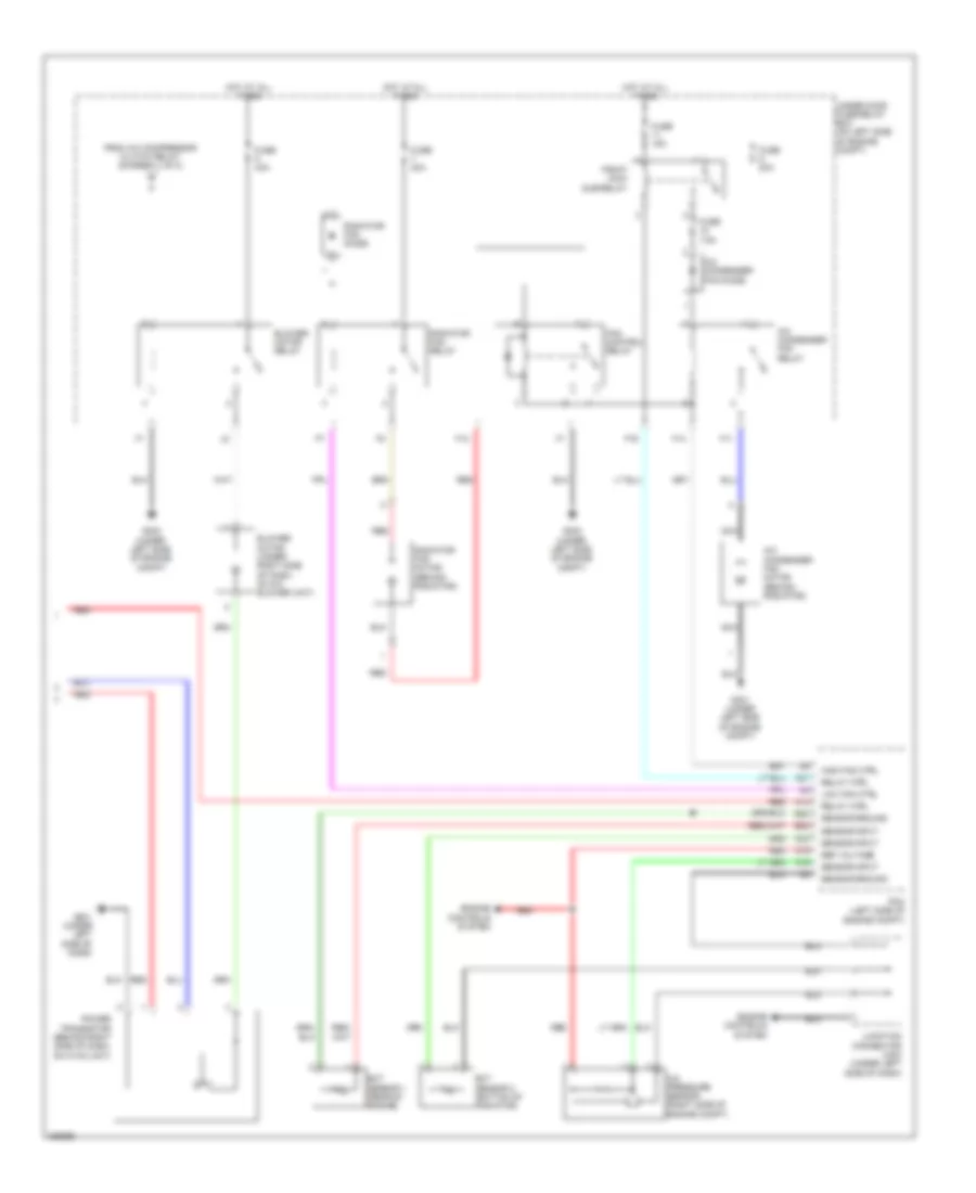
Manual A/C Wiring Diagram (2 of 2) for Honda CR-V EX 2008
List of elements for Manual A/C Wiring Diagram (2 of 2) for Honda CR-V EX 2008:
- A/c condenser fan diode
- A/c condenser fan motor (behind radiator)
- A/c condenser fan relay
- A/c pressure sensor (right side of engine compt)
- A14
- A16
- A19
- A21
- A33
- B23
- B33
- Blower motor (under right side of dash, on a/c blower unit)
- Blower motor relay
- Ect sensor 1 (rear of engine)
- Ect sensor 2 (bottom of radiator)
- Engine controls system
- F11
- F12
- F14
- F16
- Fan control relay
- From a/c compressor clutch relay (diagram 1 of 2)
- Fuse 15a
- Fuse 20a
- Fuse 40a
- Fuse 7.5a
- G301 (under left side of engine compt)
- G302 (under left side of engine compt)
- G401 (under left side of dash)
- High fan ctrl
- Hot at all times
- Junction connector c404 (under left side of dash)
- Low fan ctrl
- Nca
- Pcm (left side of engine compt)
- Pgm-fi main sub-relay
- Power transistor (behind right side of dash, on hvac unit)
- Radiator fan diode
- Radiator fan motor (behind radiator)
- Radiator fan relay
- Red
- Ref voltage
- Relay ctrl
- Sensor ground
- Sensor input
- Under-hood fuse/relay box (on left side of engine compt)