AIR CONDITIONING
Heater Wiring Diagram for Honda Fit 2010

List of elements for Heater Wiring Diagram for Honda Fit 2010:
- (under left end
- Blower motor (under right side of dash)
- Blower motor relay
- Blower resisitor (behind glove box)
- Blower switch
- Fuse 30a
- Fuse 7.5a
- G501 (under left side of dash)
- G502 (under left side of dash)
- Heater-a/c control panel
- Hot at all times
- Hot in on
- Interior lights system
- Micu
- Of dash)
- Off
- Red
- Under-dash fuse/relay box
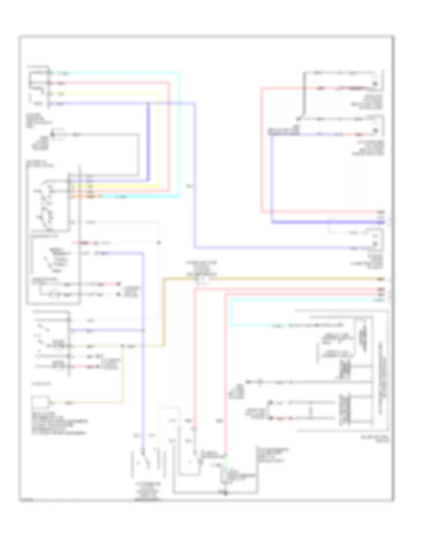
Manual A/C Wiring Diagram (1 of 2) for Honda Fit 2010
List of elements for Manual A/C Wiring Diagram (1 of 2) for Honda Fit 2010:
- (behind left side of front bumper)
- (under left side of dash) juncition connector c502
- 5v stabilizer circuit/controller area
- A/c compressor (lower right front of engine compt)
- A/c compressor clutch
- A/c condenser fan motor (behind right side of radiator)
- A/c pressure switch (lower right front of engine compt)
- A/c switch
- Blower motor (under right side of dash)
- Blower resistor (behind glove box)
- Blower switch
- Circuit dimming indicator
- Computer data lines system
- Coolant high temperature ind
- Coolant low temperature ind
- Drive circuit warning
- Fast controller area network transceiver
- G301
- G501 (under left side of dash)
- G502 (under left side of dash)
- Gauge control module
- Heater-a/c control panel
- Interior lights system
- Mode 1
- Mode 2
- Mode 3
- Mode 4
- Mode 5
- Mode control switch
- Network controller
- Off
- On ind
- Radiator fan motor (behind left side of radiator)
- Rear window defogger switch (w/o power mirror defoggers) window/ power mirror defoggers switch (w/ power mirror defoggers)
- Red
- Thermal protector
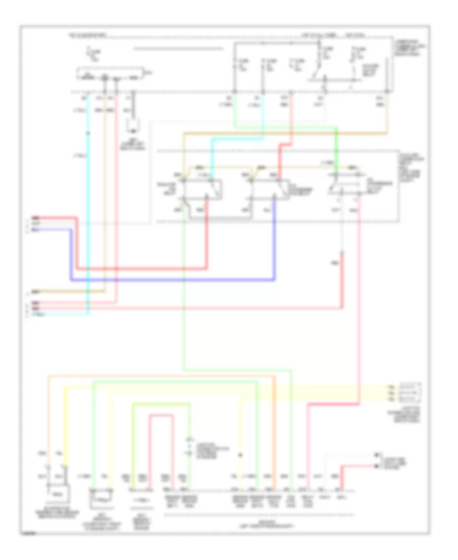
Manual A/C Wiring Diagram (2 of 2) for Honda Fit 2010
List of elements for Manual A/C Wiring Diagram (2 of 2) for Honda Fit 2010:
- (lower right front of engine compt)
- A/c compressor clutch relay
- A/c condenser fan relay
- A10
- A15
- A21
- A34
- A38
- Acs
- Auxiliary under-hood relay box (left side of engine compt)
- B12
- B15
- B24
- B34
- Blower motor relay
- Can h
- Can l
- Computer data lines system
- Ecm/pcm (left side of engine compt)
- Ect sensor 1 (rear of engine)
- Ect sensor 2
- Evaporator temperature sensor (behind glove box)
- Fan ctrl (fan)
- Fuse 30a
- Fuse 7.5a
- Fuse/relay box (under left end of dash)
- G501 (under left end of dash)
- Gnd
- Hot at all times
- Hot in on
- Hot in on or start
- Ig1 meter
- Ig2 hac
- Junction connector c103 (top rear of engine)
- Junction connector c205 (under right end of dash)
- Micu
- Pnk
- Q14
- Radiator fan relay
- Red
- Relay ctrl (acc)
- Sensor ground (sg2)
- Sensor ground (sg6)
- Sensor input (ect1)
- Sensor input (ect2)
- Sensor input (tac)
- Under-dash