AIR CONDITIONING
Automatic A/C Wiring Diagram, EX, EX-L, Touring (1 of 3) for Honda Odyssey Touring 2005

List of elements for Automatic A/C Wiring Diagram, EX, EX-L, Touring (1 of 3) for Honda Odyssey Touring 2005:
- (behind left side of front bumper) outside air temperature sensor
- (behind right rear side trim panel)
- (not used)
- (on left side of dash) in-car temperature sensor
- (on rear hvac assembly) rear blower motor
- (right side of engine compt)
- A/c pre sw
- A/c pressure switch (at right side of engine compt, on a/c receiver line)
- A/c sig
- A13
- A14
- A15
- Ac-ck
- Ac-si
- Ac-so
- Air temp sens
- Amd-p
- Amd-p as
- Amd-p dr
- Automatic lighting sensor/ sunlight sensor
- Bus data
- Bwr feedback
- Climate control panel
- Climate control unit (behind glove box)
- Control block
- D11
- Driver's air mix control motor (under left side of dash)
- Driver's under-dash fuse/relay box (under left side of dash)
- E11
- E12
- Evap temp sens
- Evaporator temperature sensor (under left side of dash)
- Ex, ex-l
- Fresh
- Front passenger's air mix control motor (under right side of dash)
- Frs
- Fuse 30a
- G202
- G504 (behind right end of dash)
- G652 (left rear of vehicle)
- Gnd
- Hot at all times
- Ig2
- Ill (+)
- Ill (-)
- Interior lights system
- J/c c506 (under middle of dash)
- J/c c507 (behind right end of dash)
- J12
- M-cool
- M-cool as
- M-cool dr
- M-def
- M-hot
- M-hot as
- M-hot dr
- M-vent
- Micu-rear junction box
- Micu-rear junction box control unit (at right "d" pillar)
- Mode 1
- Mode 2
- Mode 3
- Mode 4
- Mode control motor (behind glove box)
- Mode def
- Mode vent
- Mode1
- N22
- Navigation unit
- Passenger's under-dash fuse/relay box (under right side of dash)
- Pnk
- Pwr trns ctrl
- Rear blower motor relay
- Rec
- Recirculate
- Recirculation control motor (behind glove box, on hvac assembly)
- Red
- Relay control module
- S-com
- S5v
- Sunlight sens
- Sunlight sensor
- Temp sens
- Touring
- Under-hood fuse/relay box (right side of engine compt)
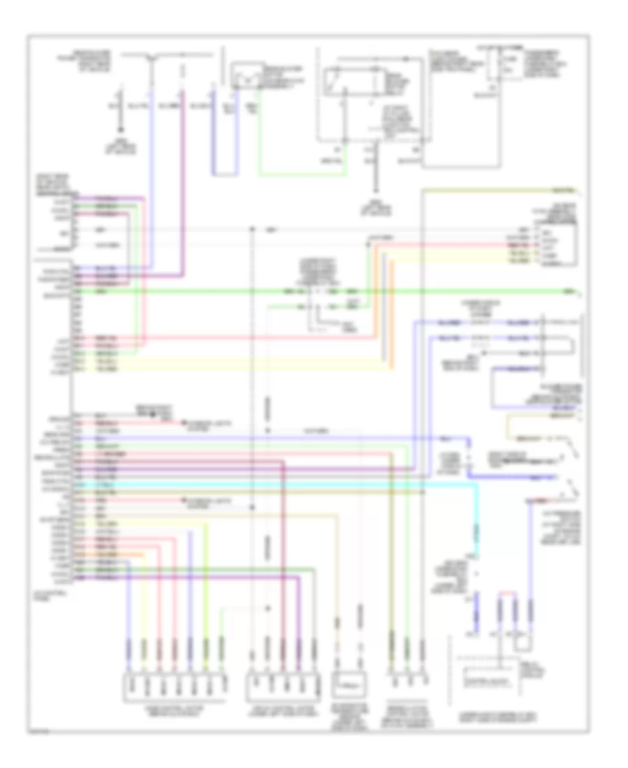
Automatic A/C Wiring Diagram, EX, EX-L, Touring (2 of 3) for Honda Odyssey Touring 2005
List of elements for Automatic A/C Wiring Diagram, EX, EX-L, Touring (2 of 3) for Honda Odyssey Touring 2005:
- (+5v)
- (right rear of vehicle)
- (under middle of dash) j/c c506
- Amd-p
- Blower motor (below glove box, on bottom of hvac assembly)
- Blower power transistor (behind glove box, near blower motor)
- Bus data
- G12
- G504 (behind right end of dash)
- G601
- G652 (left rear of vehicle)
- Gnd
- Ig2
- Ill (+)
- Ill (-)
- Interior lights system
- M-cool
- M-def
- M-hot
- M-pt
- M-vent
- Passenger's under-dash fuse/relay box (under right side of dash)
- Pwr ctrl
- R bwr fd bk
- R m-cool
- R m-def
- R m-hot
- R m-pt
- R m-vent
- R s-com
- Rear air mix control motor (right rear of vehicle)
- Rear blower power transistor (right rear of vehicle)
- Rear climate control panel
- Rear climate control unit (right rear of vehicle)
- Rear in-car temperature sensor (touring)
- Rear mode control motor (on rear hvac assembly)
- Red
- S-com
- S5v
- Trr
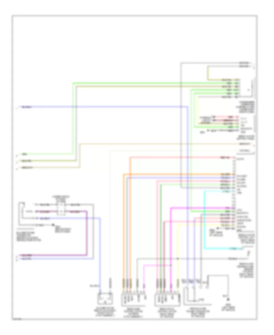
Automatic A/C Wiring Diagram, EX, EX-L, Touring (3 of 3) for Honda Odyssey Touring 2005
List of elements for Automatic A/C Wiring Diagram, EX, EX-L, Touring (3 of 3) for Honda Odyssey Touring 2005:
- A/c
- A/c compressor
- A/c compressor clutch relay
- A/c condenser fan motor
- A/c condenser fan relay
- A/c diode a
- A/c pressure switch
- A14
- A36
- A37
- Blower motor relay
- C14
- C27
- C36
- Can-l
- Compressor clutch
- Computer data lines system
- D16
- Driver's under-dash fuse/relay box (under left side of dash)
- E10
- E14
- E15
- Ect sensor 1 (at top rear of engine)
- Ect sensor 2 (below throttle body)
- F10
- F14
- F15
- F17
- F19
- Fan control relay (right front of engine compt)
- Fuse 10a
- Fuse 11 30a
- Fuse 40a
- Fuse 7.5a
- Fuse 9 30a
- G101 (at rear of engine)
- G201 (lower right front of vehicle)
- G202 (right side of engine compt)
- G301 (under left front of engine compt)
- Ground
- High fan control
- Hot at all times
- Hot in on
- Low fan control can-h
- N20
- Pcm (right side of engine compt)
- Pgm-f1 main relay 1
- Radiator fan motor
- Radiator fan relay
- Red
- Relay control
- Sensor ground
- Sensor input
- Under-hood fuse/relay box (right side of engine compt)
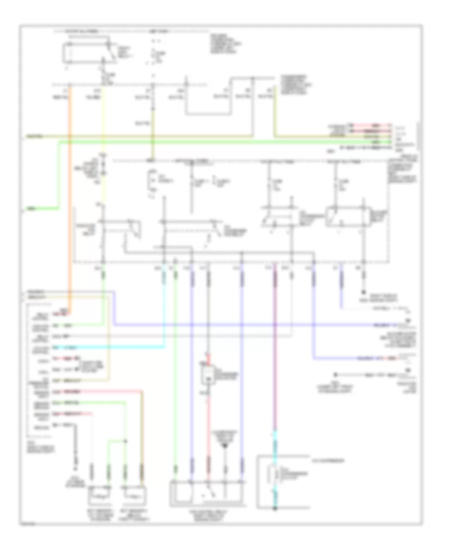
Manual A/C Wiring Diagram, LX (1 of 2) for Honda Odyssey Touring 2005
List of elements for Manual A/C Wiring Diagram, LX (1 of 2) for Honda Odyssey Touring 2005:
- (at right "d" pillar) micu-rear junction box control unit
- (behind right end of dash) g504
- (not used)
- (on rear hvac assembly) rear mode control motor
- (right rear of vehicle) rear air mix control motor
- (right side of engine compt)
- (under middle of dash) j/c c506
- (under right side of dash) passenger's under-dash fuse/relay box
- A/c control panel
- A/c pre sw
- A/c pressure switch (at right side of engine compt, on a/c receiver line)
- A/c signal
- A10
- A11
- A12
- A13
- A14
- A15
- A16
- A17
- A18
- A19
- A20
- A21
- A22
- Air mix control motor (under left side of dash)
- Amd-p
- B10
- B11
- B12
- B13
- B14
- Blower power transistor (behind glove box, near blower motor)
- Bus data
- Bwr fd bk
- Control block
- D11
- Driver's under-dash fuse/relay box (under left side of dash)
- E11
- Evap sens
- Evaporator temperature sensor (under left side of dash)
- Fresh
- Frs
- Fuse 30a
- G202
- G504 (behind right end of dash)
- G652 (left rear of vehicle)
- Ground
- Hot at all times
- Ig2
- Ill (+)
- Ill (-)
- Interior lights system
- J/c c506 (under middle of dash)
- J12
- M-cool
- M-def
- M-hot
- M-pt
- M-vent
- Micu-rear junction box (behind right rear side trim panel)
- Mode 1
- Mode 2
- Mode 3
- Mode 4
- Mode control motor (behind glove box)
- N22
- Passenger's under-dash fuse/relay box (under right side of dash)
- Pwr ctrl
- R bwr fdbk
- Rear blower motor (on rear hvac assembly)
- Rear blower motor relay
- Rear blower power transistor (right rear of vehicle)
- Rec
- Recirculate
- Recirculation control motor (behind glove box, on hvac assembly)
- Red
- Relay control module
- S-com
- S5v
- Sens gnd
- Trns ctrl
- Under-hood fuse/relay box (right side of engine compt)
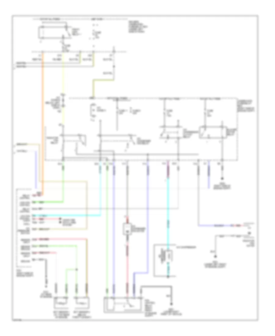
Manual A/C Wiring Diagram, LX (2 of 2) for Honda Odyssey Touring 2005
List of elements for Manual A/C Wiring Diagram, LX (2 of 2) for Honda Odyssey Touring 2005:
- (lower right front of vehicle) g201
- (right side of engine compt)
- A/c compressor
- A/c compressor clutch
- A/c compressor clutch relay
- A/c condenser fan motor
- A/c condenser fan relay
- A/c diode a
- A/c pressure switch
- A14
- A36
- A37
- Blower motor (below glove box, on bottom of hvac assembly)
- Blower motor relay
- Bus data
- C14
- C27
- C36
- Can-h
- Can-l
- Computer data lines system
- D16
- Driver's under-dash fuse/relay box (under left side of dash)
- E10
- E14
- E15
- Ect sensor 1 (at top rear of engine)
- Ect sensor 2 (below throttle body)
- F10
- F14
- F15
- F17
- F19
- Fan control relay (right front of engine compt)
- Fuse 10a
- Fuse 11 30a
- Fuse 40a
- Fuse 7.5a
- Fuse 9 30a
- G101 (at rear of engine)
- G202
- G301 (under left front of engine compt)
- G601
- Gnd
- Ground
- High fan control
- Hot at all times
- Hot in on
- Ig2
- Ill (+)
- Ill (-)
- Interior lights system
- Low fan control
- N20
- Passenger's under-dash fuse/relay box (under right side of dash)
- Pcm (right side of engine compt)
- Pgm-f1 main relay 1
- Radiator fan motor
- Radiator fan relay
- Rear a/c control panel
- Red
- Relay control
- Sensor ground
- Sensor input
- Under-hood fuse/relay box (right side of engine compt)