AIR CONDITIONING
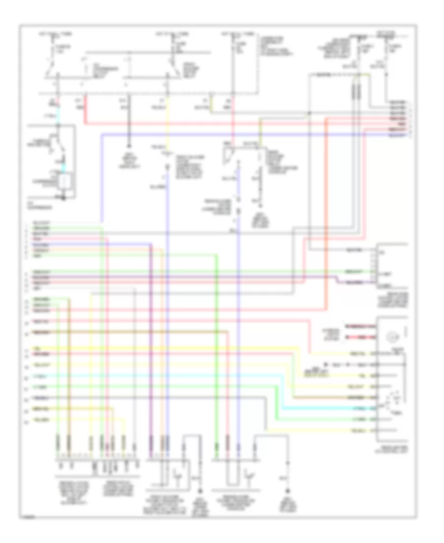
Automatic A/C Wiring Diagram (1 of 3) for Honda Pilot EX 2003

List of elements for Automatic A/C Wiring Diagram (1 of 3) for Honda Pilot EX 2003:
- A10
- A11
- A12
- A13
- A14
- A15
- A16
- A17
- A18
- A19
- A20
- Air hot mix
- Air mix cool
- Air mix potential
- Amd-p
- B10
- B11
- B12
- B13
- B14
- B15
- B16
- B17
- B18
- B19
- B20
- B21
- B22
- B23
- B24
- B25
- B26
- B27
- B28
- B29
- B30
- Blower feedback
- Climate control unit
- Defogger system
- Ect sens
- Evap temp sens
- Evaporator temperature sensor (in hvac assembly, in evaporator fins)
- Front air mix control motor (on bottom of hvac assembly)
- Front mode control motor (on left end of hvac assembly)
- G401 (behind upper left end of dash)
- Gauge assembly
- Gnd
- Ig2
- In-car temp sens
- In-car temperature sensor (on dash, right of steering column)
- Interior lights system
- M-cool
- M-def
- M-hot
- M-vent
- Mode 1
- Mode 2
- Mode 3
- Mode 4
- Mode def
- Mode vent
- Out air temp sens
- Outside air temperature sensor (on back of front bumper beam)
- Pnk
- Potential +5v
- Rear c1
- Rear c2
- Rear c3
- Rear h1
- Rear h2
- Rear h3
- Rear indicator
- Red
- S-com
- S5v
- Sens comm gnd
- Sunlight sens
- Sunlight sensor (on center of dash)
- Transistor base
- Vss
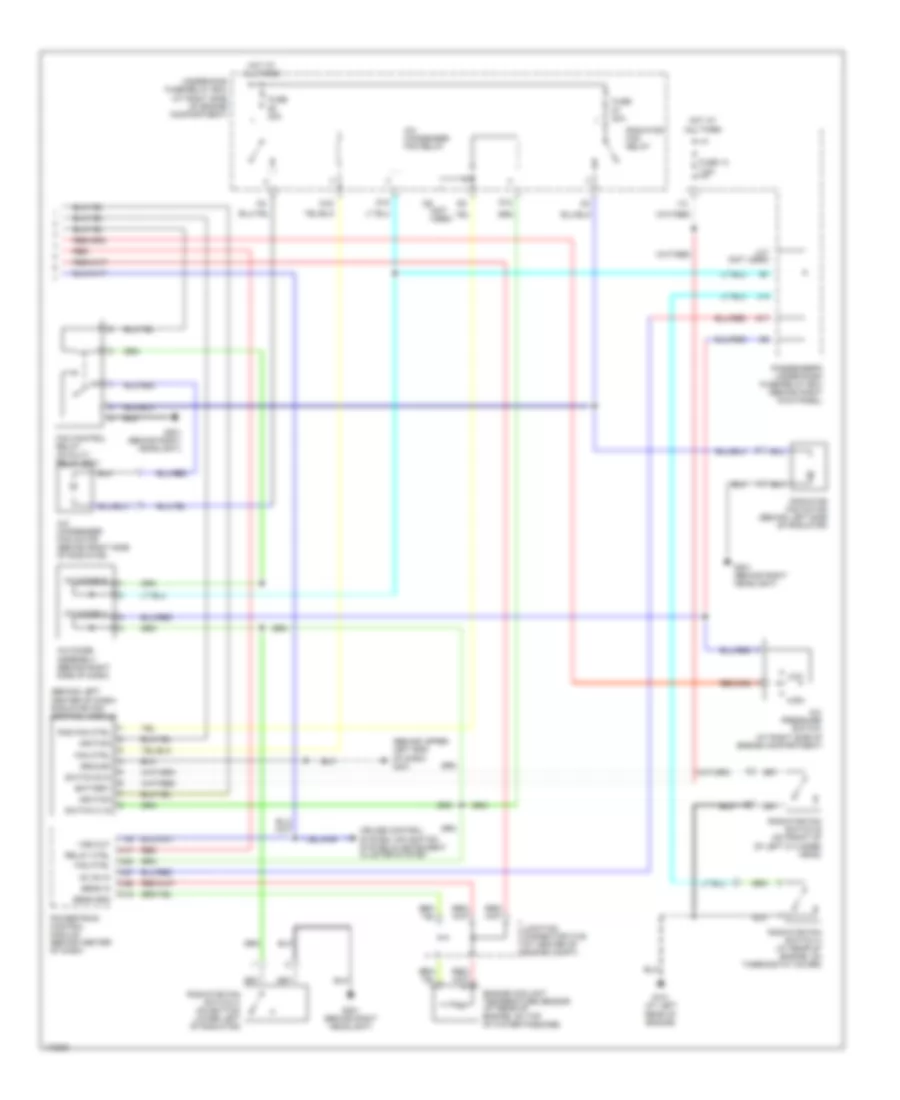
Automatic A/C Wiring Diagram (2 of 3) for Honda Pilot EX 2003
List of elements for Automatic A/C Wiring Diagram (2 of 3) for Honda Pilot EX 2003:
- 7.5a
- A/c compressor
- A/c compressor clutch
- A/c compressor clutch relay
- A10
- Amd-p
- Cool
- D11
- D14
- Front blower motor (under right side of dash, on bottom of blower unit)
- Front blower motor relay
- Front blower power transistor (on bottom of blower unit, next to front blower motor)
- Frs
- Fuse 3 7.5a
- Fuse 30a
- Fuse 40a
- Fuse 59
- Fuse 6 15a
- G201 (behind right headlight)
- G401 (behind upper left end of dash)
- G501 (behind left end of dash)
- Hot
- Hot at all times
- Hot in on driver's under-dash fuse/relay box (behind left end of dash)
- Hot in on or start
- Ig2
- Interior lights system
- M-cool
- M-heat
- M-hot
- M-vent
- M14
- Nca
- Off
- On ind
- Pnk
- Rear air mix control motor (under center console panel)
- Rear blower motor (under center console)
- Rear blower motor relay (under center console)
- Rear blower power transistor (under center console)
- Rear heater- a/c control unit
- Rear mode control motor (under center console panel)
- Rec
- Recirculation control motor (behind glove box, on left side of blower unit)
- Red
- S-com
- S5v
- Thermal protector
- Under-hood fuse/relay box (at right side of engine compt)
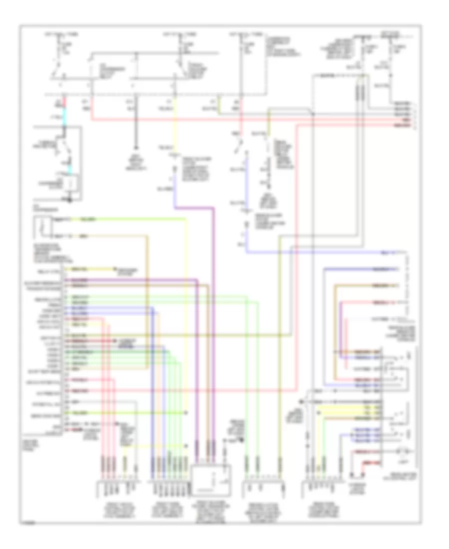
Automatic A/C Wiring Diagram (3 of 3) for Honda Pilot EX 2003
List of elements for Automatic A/C Wiring Diagram (3 of 3) for Honda Pilot EX 2003:
- (at right side of engine compartment)
- (behind left center of dash) radiator fan control module
- (behind upper left end of dash) g401
- A/c condenser fan motor (behind right side of radiator)
- A/c condenser fan relay
- A/c diode a
- A/c diode assembly (behind right side of dash)
- A/c diode b
- A/c pressure switch
- A17 red
- Ac on in
- Battery
- Cruise control system, navigation system & instrument cluster system
- D12
- D15
- D16
- D9 (not used)
- Engine coolant temperature sensor (at rear of engine, on top of water passage)
- Fan control relay (in multi- relay box)
- Fan ctrl
- Fuse 13 7.5a
- Fuse 30a
- G101 (at left rear of engine)
- G17
- G201 (behind right headlight)
- Ground
- H17 (not used)
- High
- Hot at all times
- I12
- Ignition
- J14
- Junction connector c105 (at center of engine compt)
- Low
- Passenger's under-dash fuse/relay box (behind right kick panel)
- Powertrain control module (behind center of dash)
- Rad fan ctrl
- Radiator fan motor (behind left side of radiator)
- Radiator fan relay
- Radiator fan switch a (at rear of engine, on thermostat cover)
- Radiator fan switch b (on front of of left cylinder head)
- Radiator fan switch c (on bottom lower left of radiator)
- Red
- Relay ctrl
- Sens gnd
- Sens in
- Switch b in
- Switch c in
- Underhood fuse/relay box (at right side of engine compartment)
- Vss out
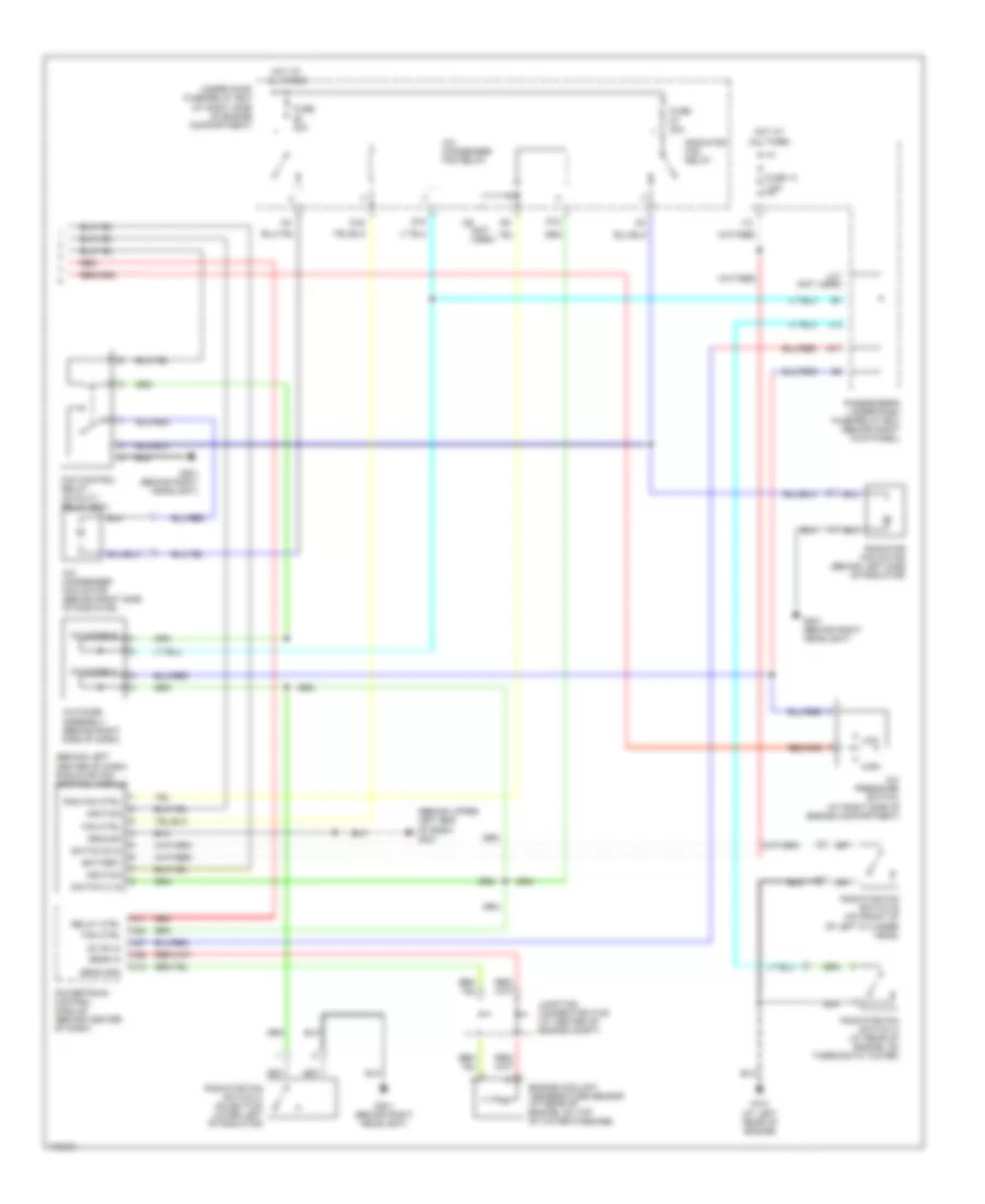
Manual A/C Wiring Diagram (1 of 2) for Honda Pilot EX 2003
List of elements for Manual A/C Wiring Diagram (1 of 2) for Honda Pilot EX 2003:
- (behind upper left end of dash) g401
- 7.5a
- A/c compressor
- A/c compressor clutch
- A/c compressor clutch relay
- A/c pres sw
- A10
- Air mix cool
- Air mix hot
- Air mix potential
- Amd-p
- Blower feedback
- Cool
- D11
- D14
- Defogger system
- Driver's under-dash fuse/relay box (behind left end of dash)
- Evap temp sens
- Evaporator temperature sensor (in hvac assembly, in evaporator fins)
- Fresh
- Front air mix control motor (on bottom of hvac assembly)
- Front blower motor (under right side of dash, on bottom of blower unit)
- Front blower motor relay
- Front blower power transistor (on bottom of blower unit, next to front blower motor)
- Front mode control motor (on left end of hvac assembly)
- Frs
- Fuse
- Fuse 3 7.5a
- Fuse 30a
- Fuse 40a
- Fuse 6 15a
- G201 (behind right headlight)
- G401 (behind upper left end of dash)
- G501 (behind left end of dash)
- Gnd
- Heater control panel
- Hot
- Hot at all times
- Hot in on
- Hot in on or start
- Ig2
- Ign
- Ignition in
- Illumi (+)
- Illumi (-)
- Interior lights system
- Light
- M-cool
- M-def
- M-hot
- M-vent
- M14
- Mode 1
- Mode 2
- Mode 3
- Mode 4
- Mode def
- Mode vent
- Nca
- Potential +5v
- Rear blower motor (under center console)
- Rear blower motor relay (under center console)
- Rear blower resistor (under center console)
- Rear heater a/c control unit
- Rear mode control motor (under center console panel)
- Rec
- Recirculate
- Recirculation control motor (behind glove box, on left side of blower unit)
- Red
- Relay ctrl
- S-com
- S5v
- Sens comm gnd
- Thermal protector
- Transistor base
- Underhood fuse/relay box (at right side of engine compt)
- Vent
Manual A/C Wiring Diagram (2 of 2) for Honda Pilot EX 2003
List of elements for Manual A/C Wiring Diagram (2 of 2) for Honda Pilot EX 2003:
- (at right side of engine compartment)
- (behind left center of dash) radiator fan control module
- (behind upper left end of dash) g401
- A/c condenser fan motor (behind right side of radiator)
- A/c condenser fan relay
- A/c diode a
- A/c diode assembly (behind right side of dash)
- A/c diode b
- A/c pressure switch
- A17 red
- Ac on in
- Battery
- D12
- D15
- D16
- D9 (not used)
- Engine coolant temperature sensor (at rear of engine, on top of water passage)
- Fan control relay (in multi- relay box)
- Fan ctrl
- Fuse 13 7.5a
- Fuse 30a
- G101 (at left rear of engine)
- G17
- G201 (behind right headlight)
- Ground
- H17 (not used)
- High
- Hot at all times
- I12
- Ignition
- J14
- Junction connector c105 (at center of engine compt)
- Low
- Passenger's under-dash fuse/relay box (behind right kick panel)
- Powertrain control module (behind center of dash)
- Rad fan ctrl
- Radiator fan motor (behind left side of radiator)
- Radiator fan relay
- Radiator fan switch a (at rear of engine, on thermostat cover)
- Radiator fan switch b (on front of of left cylinder head)
- Radiator fan switch c (on bottom lower left of radiator)
- Red
- Relay ctrl
- Sens gnd
- Sens in
- Switch b in
- Switch c in
- Under-hood fuse/relay box (at right side of engine compartment)