AIR CONDITIONING
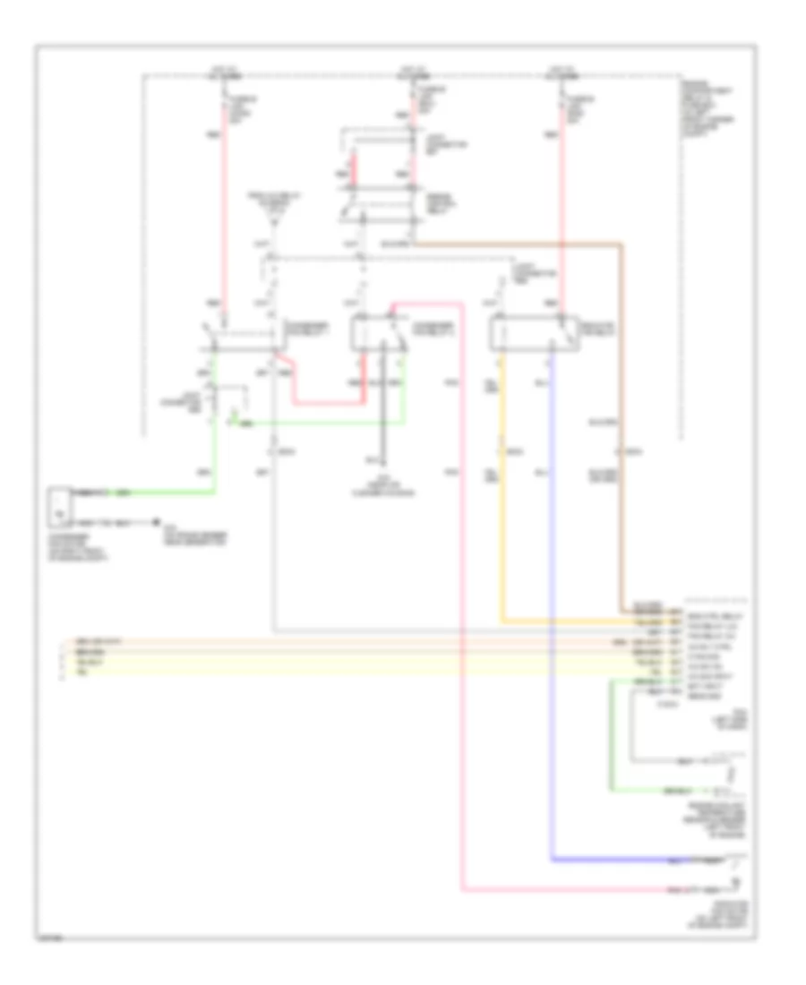
Automatic A/C Wiring Diagram (1 of 2) for Hyundai Elantra GT 2005

List of elements for Automatic A/C Wiring Diagram (1 of 2) for Hyundai Elantra GT 2005:
- (behind left center of dash) mode actuator
- (beside blower motor, below right side of dash) blower relay
- A/c control module (below center of dash, forward of shift lever)
- A/c output
- A/c select
- Actuator cool
- Actuator warm
- Amb temp sens
- Ambient sensor (behind center of front bumper)
- Aqs sensor
- Aqs sensor (behind center of front bumper, on cross support)
- Blower motor (under right side of dash)
- Blr feed back
- Def
- Defogger
- Defogger sw
- Engine compartment relay & fuse box (in left front corner of engine compartment)
- Feed back sig
- Fre
- Fuse 10a
- Fuse 15a
- Fusible link (blower) 30a
- G11 (behind center of dash)
- G11 (behind center of dash)
- G15 (near air cleaner housing)
- Ground
- Hi blwr ctrl
- High blower relay (beside blower motor, below right side of dash)
- Hot at all times
- Hot in on
- Humidity sensor
- Humidity sensor (4 door: left center of rear package shelf) (5 door: right rear shock tower)
- I/p-b
- I/p-g
- I/p-h
- I/p-j
- Ill+
- Ill-
- In-car sens in
- In-car sens out
- Interior lights system
- Joint connector e56
- Joint connector m33 (left side of dash)
- Joint connector m36 (left side of dash)
- M19-1
- M19-2
- Memory power
- On input
- Passenger compartment junction block (under left side of dash, near kick panel)
- Photo sens +
- Pnk
- Power (5v)
- Power transistor (under right side of dash, in blower motor housing)
- Pwr trans
- Rec
- Red
- Sensor ground
- Sensor signal
- System
- Temperature actuator (behind lower right center of dash)
- Vent
Automatic A/C Wiring Diagram (2 of 2) for Hyundai Elantra GT 2005
List of elements for Automatic A/C Wiring Diagram (2 of 2) for Hyundai Elantra GT 2005:
- (on frame member, near generator) g16
- A/c compressor (right front of engine)
- A/c relay
- A/c relay ctrl
- A/c sig input
- A/c sw on
- C fan sig
- C183-3
- Condenser fan motor (on right front of engine compt)
- Condenser fan relay 1
- Condenser fan relay 2
- Ec03
- Ec04
- Ect input
- Engine compartment relay & fuse box (in left front corner of engine compartment)
- Engine control relay
- Engine coolant temperature sensor & sender (left front of engine)
- Engine ctrl rly
- Evaporator temperature sensor (behind lower left center of dash)
- Fan relay (hi)
- Fan relay (lo)
- Fusible link (cond) 20a
- Fusible link (ecu) 20a
- Fusible link (rad) 20a
- G15 (near air cleaner housing)
- High
- Horn & a/c fuse 15a
- Hot at all times
- Intake actuator
- Joint connector e57
- Joint connector e58
- Joint connector e59
- Low
- Mid
- Nca
- Pcm (left side of dash)
- Photo sensor (on top right side of dash, near defroster vent)
- Pnk
- Radiator fan motor (on left front of engine compt)
- Radiator fan relay
- Red
- Sens gnd
- Triple pressure switch (on a/c line, near right front strut tower)
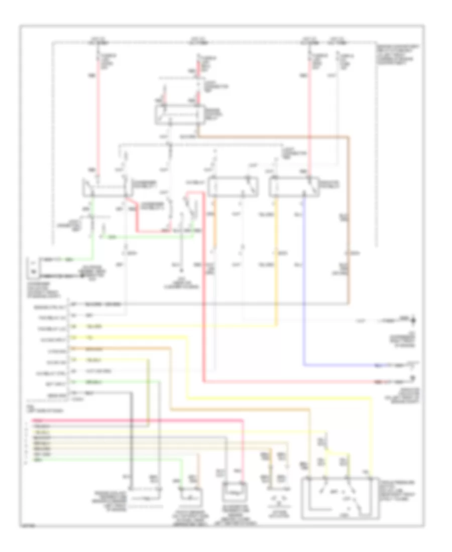
Manual A/C Wiring Diagram (1 of 2) for Hyundai Elantra GT 2005
List of elements for Manual A/C Wiring Diagram (1 of 2) for Hyundai Elantra GT 2005:
- (beside blower motor, below right side of dash) blower relay
- A/c compressor (right front of engine)
- A/c control module (below center of dash, forward of shift lever)
- A/c on sig
- A/c relay
- Actuator
- Blower motor (under right side of dash)
- Blower resistor (under right side of dash, in blower motor housing)
- Blower switch
- Blr on sig
- Cool
- Defog switch
- Defogger system
- Ec03
- Engine compartment relay & fuse box (in left front corner of engine compt)
- F/b
- F/b ground
- Fre
- Fuse 10a
- Fuse 15a
- Fusible link (blower) 30a
- G11 (behind center of dash)
- Ground
- High
- Horn & a/c fuse 15a
- Hot at all times
- Hot in on
- I/p-g
- I/p-h
- I/p-j
- Iii
- Iiii
- Illum +
- Illum -
- Intake actuator (behind upper right side of dash)
- Interior lights system
- Joint connector m36 (left side of dash)
- Low
- Mem pwr
- Mid
- Mode actuator (behind left center of dash)
- Nca
- Off
- On input
- Passenger compartment junction block (under left side of dash, near kick panel)
- Pnk
- Rec
- Red
- Temperature actuator (behind lower left center of dash)
- Thermistor
- Thermostatic switch (behind right side of dash)
- To joint connector e58 (diagram 2 of 2)
- Triple pressure switch (on a/c line, near right front strut tower)
- Vcc
- Warm
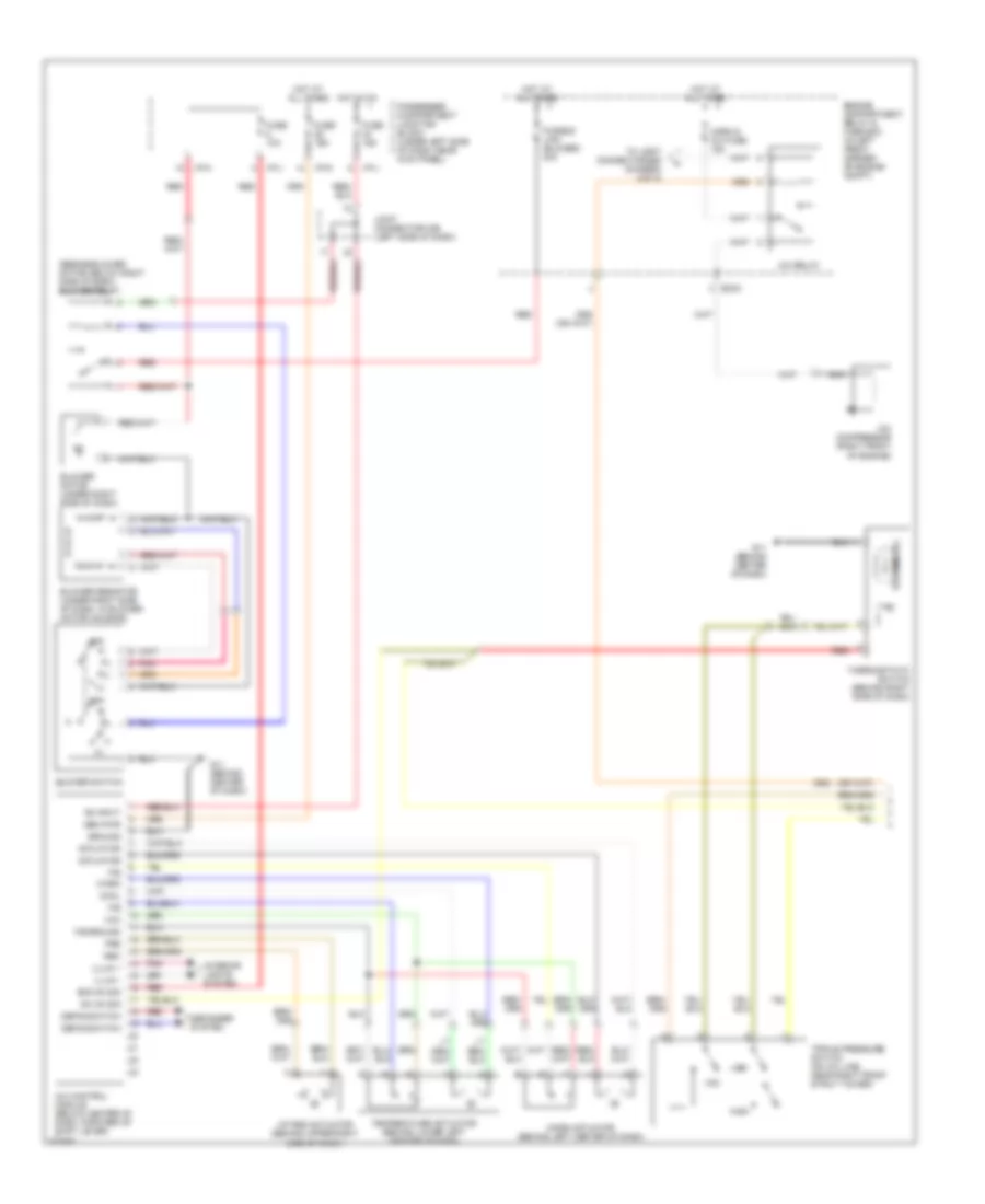
Manual A/C Wiring Diagram (2 of 2) for Hyundai Elantra GT 2005
List of elements for Manual A/C Wiring Diagram (2 of 2) for Hyundai Elantra GT 2005:
- A/c rly ctrl
- A/c sig input
- A/c sw on
- C fan sig
- C183-3
- Condenser fan motor (on right front of engine compt)
- Condenser fan relay 1
- Condenser fan relay 2
- Ec03
- Ec04
- Ect input
- Eng ctrl relay
- Engine compartment relay & fuse box (in left front corner of engine compt)
- Engine control relay
- Engine coolant temperature sensor & sender (left front of engine)
- Fan relay (hi)
- Fan relay (lo)
- From a/c relay (diagram 1 of 2)
- Fusible link (cond) 20a
- Fusible link (ecu) 20a
- Fusible link (rad) 20a
- G15 (near air cleaner housing)
- G16 (on frame member, near generator)
- Hot at all times
- Joint connector e57
- Joint connector e58
- Joint connector e59
- Nca
- Pcm (left side of dash)
- Pnk
- Radiator fan motor (on left front of engine compt)
- Radiator fan relay
- Red
- Sens gnd