AIR CONDITIONING
2.0L TURBO
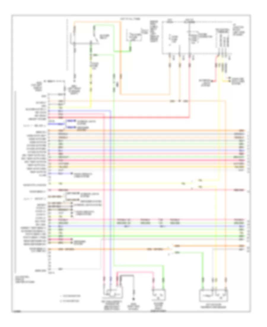
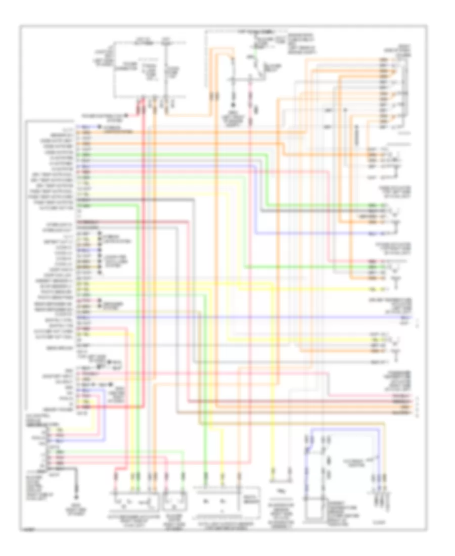
2.0L Turbo, Automatic A/C Wiring Diagram (1 of 3) for Hyundai Sonata Hybrid 2014

List of elements for 2.0L Turbo, Automatic A/C Wiring Diagram (1 of 3) for Hyundai Sonata Hybrid 2014:
- A/c control module (center of dash)
- A/con fuse 10a
- A/con fuse 7.5a
- Active incar temperature sensor
- Ambient temp sens (+)
- B-can hi
- B-can lo
- Blower fuse 40a
- Blower motor (+)
- Blower motor (right side of dash)
- Blower relay
- C-can hi
- C-can lo
- Clk vref (5v)
- Computer data lines system
- Defogger system
- Detent
- Drv temp actr cool
- Drv temp actr f/b
- Drv temp actr warm
- Ec11
- Ecv gnd
- Ecv pwr
- Em11
- Em61
- Engine room fuse & relay box (left rear of engine compt)
- Evaporator sens (+)
- Exterior lights system
- Fet (field effect) transistor (behind right side of dash)
- Fet drain
- Fet gate
- Ge01 (left front of engine compt)
- Gm02 (right end of dash)
- Gm03 (top left side of dash)
- Gnd
- Haz sw sig
- Hot at all times
- Hot in on
- I/p junction block (left side of dash)
- I/p-b
- I/p-e
- I/p-f
- I/p-g
- Ill (+)
- Ill (-)
- Incar mtr (-)/haz sig
- Incar sens (+)
- Incar sens (+)/
- Intake actr f/b
- Intake actr fre
- Intake actr rec
- Interior lights system
- Ips control module
- K-line
- M-can hi
- M-can lo
- M21-a
- M21-b
- Memory power
- Mode actr def
- Mode actr f/b
- Mode actr vent
- Multi fuse
- On input
- Photo sens (-) dri
- Photo sens (-) pass
- Pnk
- Power connector
- Rear defogger ind
- Rear defogger sw
- Red
- Room lamp fuse 10a
- Sens (5v)
- Sens gnd
- Temp actr cool
- Temp actr f/b
- Temp actr warm
- W/ navigation
- W/o navigation
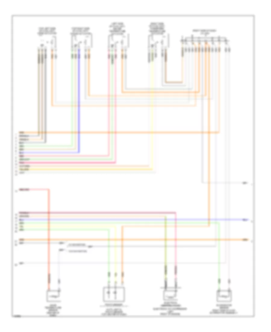
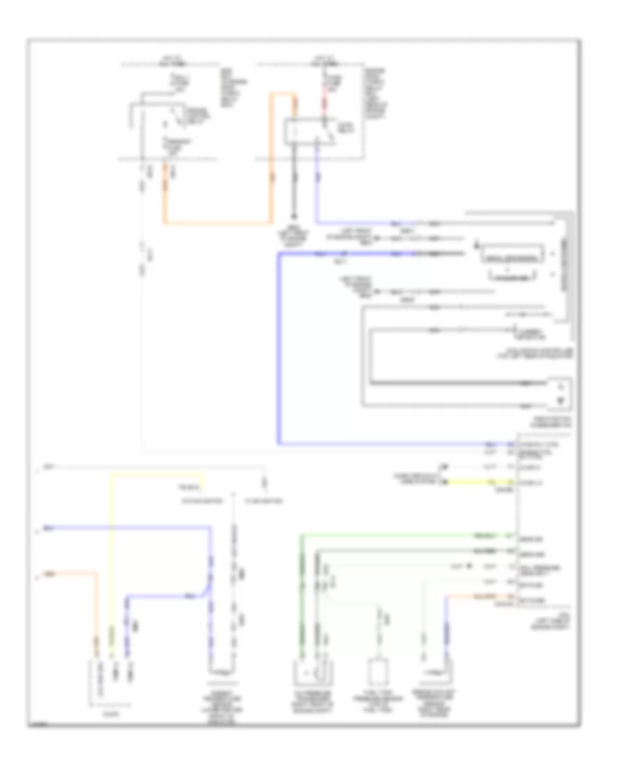
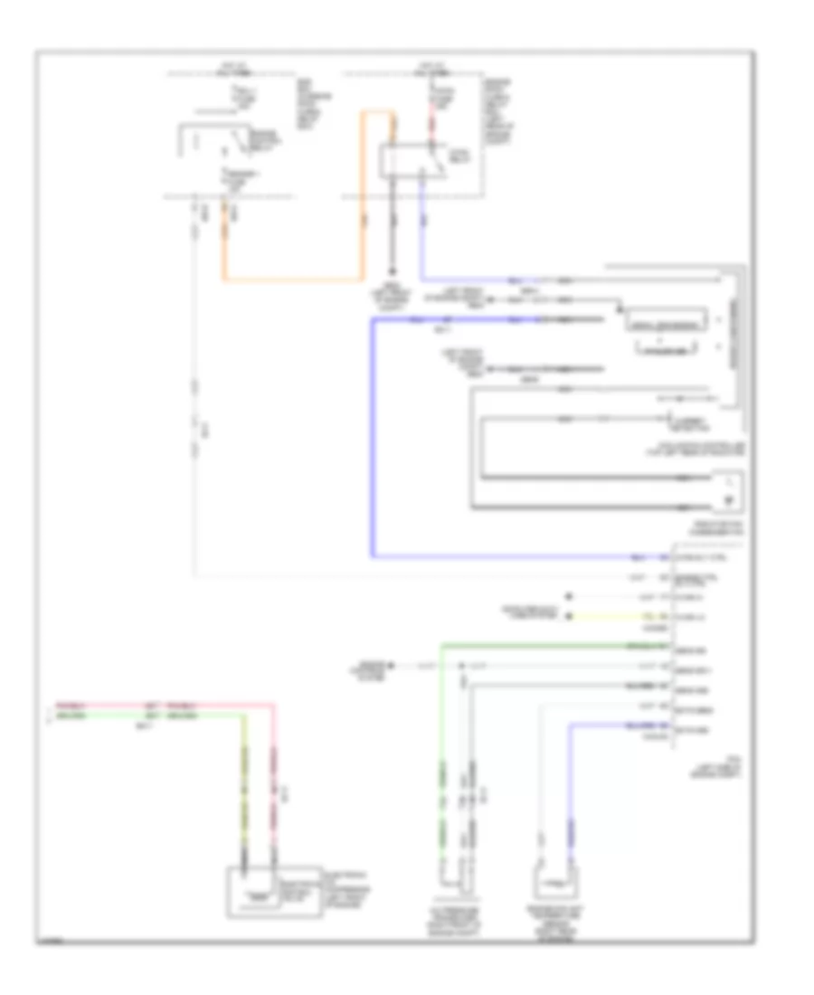
2.0L Turbo, Automatic A/C Wiring Diagram (2 of 3) for Hyundai Sonata Hybrid 2014
List of elements for 2.0L Turbo, Automatic A/C Wiring Diagram (2 of 3) for Hyundai Sonata Hybrid 2014:
- (left side of hvac unit) driver temperature actuator
- (right side of dash) j/c jm04
- (right side of hvac unit) passenger temperature actuator
- (top left side of hvac unit) mode actuator
- (top right side of hvac unit) intake actuator
- Auto light & photo sensor (top center of dash)
- Electrical control valve
- Electronic a/c compressor (left front of engine)
- Evaporator sensor (right side of hvac evaporator assembly)
- Incar temperature sensor (center of dash)
- Nca
- Photo sensor
- Pnk
- Red
- W/ navigation
- W/o navigation
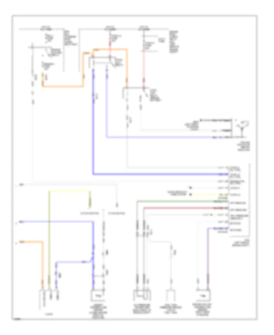
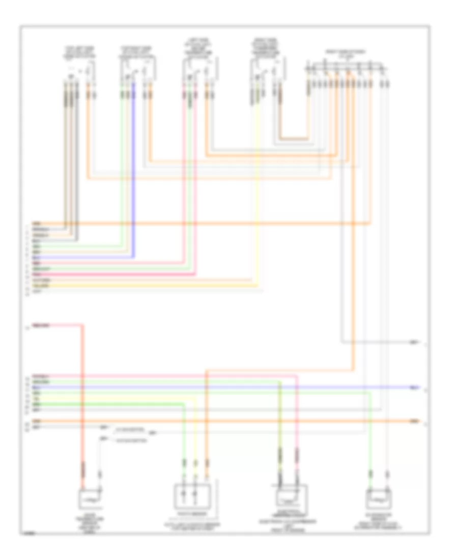
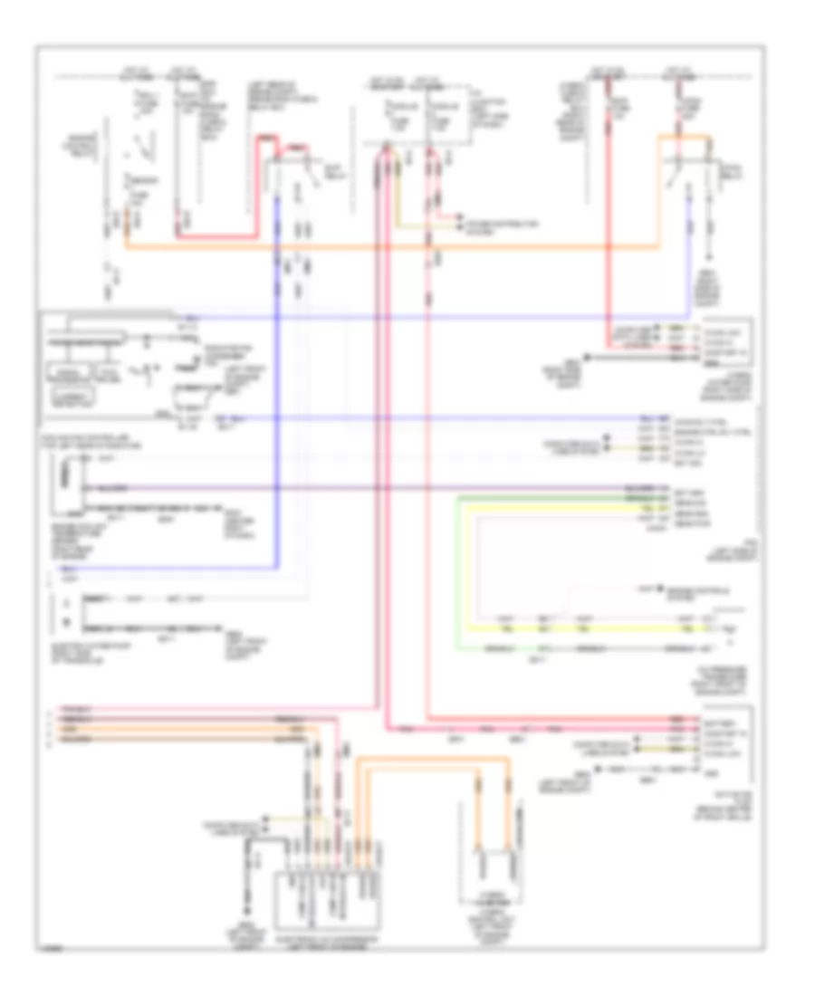
2.0L Turbo, Automatic A/C Wiring Diagram (3 of 3) for Hyundai Sonata Hybrid 2014
List of elements for 2.0L Turbo, Automatic A/C Wiring Diagram (3 of 3) for Hyundai Sonata Hybrid 2014:
- A/c pressure transducer (right front of engine compt)
- Ambient temperature sensor (lower center front of radiator)
- Apt sens gnd
- Apt sens sig
- C-can hi
- C-can lo
- C/fan hi fuse 60a
- C/fan hi rly ctrl
- C/fan high relay (beside battery)
- C/fan lo fuse 40a
- C/fan lo rly ctrl
- C/fan low relay
- Chtg-ag
- Chtg-bg
- Clk vref (5v)
- Clock
- Computer data lines system
- Cooling fan motor (behind radiator)
- E/r-a
- E/r-b
- Ec11
- Ects gnd
- Ects sig
- Ecu 1 fuse 30a
- Ee01
- Ef01
- Em61
- Ems box (in engine room fuse & relay box)
- Engine control relay
- Engine coolant temperature sensor (right rear of engine)
- Engine ctrl rly ctrl
- Engine room fuse & relay box (left rear of engine compt)
- Fuel tank pressure sensor (top of fuel tank)
- Ge02 (left front of engine compt)
- Hot at all times
- Multi fuse
- Nca
- Pcm (left side of engine compt)
- Rail pressure sens sply
- Red
- Sensor 1 fuse 15a
- Temp (+)
- Temp (-)
- W/ navigation
- W/o navigation
2.4L
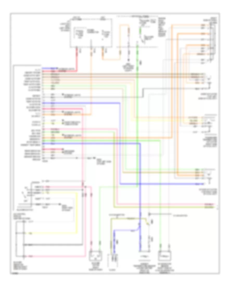
2.4L, Automatic A/C Wiring Diagram, Except Hybrid (1 of 3) for Hyundai Sonata Hybrid 2014
List of elements for 2.4L, Automatic A/C Wiring Diagram, Except Hybrid (1 of 3) for Hyundai Sonata Hybrid 2014:
- A/c control module (center of dash)
- A/con fuse 10a
- A/con fuse 7.5a
- Active incar temperature sensor
- Ambient temp sens (+)
- B-can hi
- B-can lo
- Blower fuse 40a
- Blower motor (+)
- Blower motor (right side of dash)
- Blower relay
- C-can hi
- C-can lo
- Clk vref (5v)
- Computer data lines system
- Defogger system
- Detent
- Drv temp actr cool
- Drv temp actr f/b
- Drv temp actr warm
- Ec11
- Ecv gnd
- Ecv pwr
- Em11
- Em61
- Engine room fuse & relay box (left rear of engine compt)
- Evaporator sens (+)
- Exterior lights system
- Fet (field effect) transistor (behind right side of dash)
- Fet drain
- Fet gate
- Ge01 (left front of engine compt)
- Gm02 (right end of dash)
- Gm03 (top left side of dash)
- Gnd
- Haz sw sig
- Hot at all times
- Hot in on
- I/p junction block (left side of dash)
- I/p-b
- I/p-e
- I/p-f
- I/p-g
- Ill (+)
- Ill (-)
- Incar mtr (-)/haz sig
- Incar sens (+)
- Incar sens (+)/
- Ind out
- Intake actr f/b
- Intake actr fre
- Intake actr rec
- Interior lights system
- Ips control module
- K-line
- M-can hi
- M-can lo
- M21-a
- M21-b
- Memory power
- Mode actr def
- Mode actr f/b
- Mode actr vent
- Multi fuse
- On input
- Photo sens (-) dri
- Photo sens (-) pass
- Pnk
- Power connector
- Rear defogger ind
- Rear defogger sw
- Red
- Room lamp fuse 10a
- Sel sig
- Sens (5v)
- Sens gnd
- Temp actr cool
- Temp actr f/b
- Temp actr warm
- W/ navigation
- W/o navigation
2.4L, Automatic A/C Wiring Diagram, Except Hybrid (2 of 3) for Hyundai Sonata Hybrid 2014
List of elements for 2.4L, Automatic A/C Wiring Diagram, Except Hybrid (2 of 3) for Hyundai Sonata Hybrid 2014:
- (left side of hvac unit) driver temperature actuator
- (right side of dash) j/c jm04
- (right side of hvac unit) passenger temperature actuator
- (top left side of hvac unit) mode actuator
- (top right side of hvac unit) intake actuator
- Auto light & photo sensor (top center of dash)
- Electrical control valve
- Electronic a/c compressor (left front of engine)
- Evaporator sensor (right side of hvac evaporator assembly)
- Incar temperature sensor (center of dash)
- Nca
- Photo sensor
- Pnk
- Red
- W/ navigation
- W/o navigation
2.4L, Automatic A/C Wiring Diagram, Except Hybrid (3 of 3) for Hyundai Sonata Hybrid 2014
List of elements for 2.4L, Automatic A/C Wiring Diagram, Except Hybrid (3 of 3) for Hyundai Sonata Hybrid 2014:
- (left front of engine compt) ge02
- A/c pressure transducer (right front of engine compt)
- Ambient temperature sensor (lower center front of radiator)
- C-can hi
- C-can lo
- C/fan fuse 50a
- C/fan relay
- C/fan rly ctrl
- Chg-ag
- Chg-bg
- Clk vref (5v)
- Clock
- Computer data lines system
- Cooling fan controller (top left rear of radiator)
- Current detecting
- E/r-a
- E/r-b
- E36-a
- E36-b
- Ec11
- Ects gnd
- Ects sig
- Ecu 1 fuse 30a
- Ee01
- Ef01
- Em61
- Ems box (in engine room fuse & relay box)
- Engine control relay
- Engine coolant temperature sensor (right rear of engine)
- Engine ctrl rly ctrl
- Engine room fuse & relay box (left rear of engine compt)
- Fuel tank pressure sensor (top of fuel tank)
- Ge02 (left front of engine compt)
- Hot at all times
- Nca
- Pcm (left side of engine compt)
- Power conditioning
- Pwn driver
- Radiator fan/ condenser fan
- Rail pressure sens sply
- Red
- Sens gnd
- Sens sig
- Sensor 1 fuse 15a
- Signal processing
- Temp (+)
- Temp (-)
- W/ navigation
- W/o navigation
2.4L, Automatic A/C Wiring Diagram, Hybrid (1 of 2) for Hyundai Sonata Hybrid 2014
List of elements for 2.4L, Automatic A/C Wiring Diagram, Hybrid (1 of 2) for Hyundai Sonata Hybrid 2014:
- (+)
- (-)
- (right side of dash) j/c jm04
- (top left side of dash) gm03
- A/c control module (center of dash)
- A/con fuse 7.5a
- Ambient sensor (+)
- Ambient temperature sensor (lower center front of radiator)
- Auto def act cool
- Auto def act f/b
- Auto def act warm
- Auto defogger actuator (right side of hvac unit)
- Auto light & photo sensor (top center of dash)
- Blower fuse 40a
- Blower motor (right side of dash)
- Blower motor control module (right side of hvac unit)
- Blower relay
- C-can hi
- C-can lo
- Clock
- Clock 5v
- Comp can hi
- Comp can low
- Computer data lines system
- Defogger system
- Detent out (+)
- Driver temperature actuator (left side of hvac unit)
- Drv temp actr cool
- Drv temp actr f/b
- Drv temp actr warm
- Ee01
- Em61
- Engine room fuse & relay box (left rear of engine compt)
- Evap sensor (+)
- Evaporator sensor (right side of hvac evaporator assembly)
- Ewp rly ctrl
- Ewp rly f/b
- Ge02 (left front of engine compt)
- Gm02 (right end of dash)
- Gm04 (center right of dash)
- Gnd
- Hot at all times
- Hot in on
- I/p junction box (left side of dash)
- I/p-b
- I/p-e
- I/p-g
- Ill (+)
- Ill (-)
- In actr f/b
- In actr fre
- In actr rec
- Inh
- Intake actuator (top right side of hvac unit)
- Interior lights system
- Interlock in
- Interlock out
- M-can hi
- M-can lo
- M21-a
- M21-b
- M27-p
- M27-s
- Memory power
- Mode actr def
- Mode actr f/b
- Mode actr vent
- Mode actuator (top left side of hvac unit)
- Monitor
- Multi fuse
- On input
- On/start input
- Pass temp actr cool
- Pass temp actr f/b
- Pass temp actr warm
- Passenger temperature actuator (right side of hvac unit)
- Photo sens dri
- Photo sens pass
- Photo sensor
- Pnk
- Power connector
- Power distribution system
- Pwn in
- Rear defogger ind
- Rear defogger sw
- Red
- Room lamp fuse 10a
- Sens ground
- Sensor (5v)
- Temp(+)
- Temp(-)
- W/o front
2.4L, Automatic A/C Wiring Diagram, Hybrid (2 of 2) for Hyundai Sonata Hybrid 2014
List of elements for 2.4L, Automatic A/C Wiring Diagram, Hybrid (2 of 2) for Hyundai Sonata Hybrid 2014:
- (left front of engine compt) ge01
- (left rear of engine compt) engine room fuse & relay box
- A/c pressure transducer (right front of engine compt)
- Active air flap (behind center of front grille)
- Battery
- C-can hi
- C-can lo
- C-can low
- C/fan fuse 60a
- C/fan relay
- C/fan rly ctrl
- Chg-k
- Chg32-p
- Chg32-s
- Chg34-comp
- Comp can hi
- Comp can lo
- Computer data lines system
- Cooling fan controller (top left rear of radiator)
- Current detecting
- E/r-a
- E/r-b
- E11-a
- E11-b
- Ec11
- Ect gnd
- Ect sig
- Ecu 1 fuse 30a
- Ee01
- Ef01
- Electric water pump (right side of transaxle)
- Electronic a/c compressor (left front of engine)
- Em11
- Em61
- Ems box (in engine room fuse & relay box)
- Engine control relay
- Engine controls system
- Engine coolant temperature sensor (right rear of engine)
- Engine ctrl rly ctrl
- Ewp fuse 10a
- Ewp relay
- Fan
- Ge04 (right side of engine compt)
- Ge08 (left front of engine compt)
- Gm04 (center right of dash)
- Gnd
- Hot at all times
- Hot at all times red
- Hot in on or start
- Hot in on or start red
- Hybrid control unit (left front of engine compt)
- Hybrid fuse & relay box (right rear of engine compt)
- Hybrid inverter
- Hybrid water pump (right side of engine compt)
- I/p junction box (left side of dash)
- I/p-e
- I/p-g
- Interlock in
- Interlock out
- Module fuse 7.5a
- Nca
- On/start in
- Out
- Pcm (left side of engine compt)
- Pnk
- Power
- Power conditioning
- Power distribution system
- Pwn driver
- Radiator fan condenser m
- Red
- Sens gnd
- Sens pwr
- Sens sig
- Sensor
- Sensor fuse 15a
- Signal processing
2.4L, Manual A/C Wiring Diagram, Except Hybrid (1 of 2) for Hyundai Sonata Hybrid 2014
List of elements for 2.4L, Manual A/C Wiring Diagram, Except Hybrid (1 of 2) for Hyundai Sonata Hybrid 2014:
- (right side of dash) j/c jm04
- A/c control module (center of dash)
- A/con fuse 7.5a
- Ambient temp sens
- Ambient temperature sensor (lower center front of radiator)
- Blower comm
- Blower f/b
- Blower fuse 40a
- Blower motor (right side of dash)
- Blower relay
- Blower resistor (behind right side of dash)
- Blower switch
- C-can hi
- C-can lo
- Clock
- Common
- Computer data lines system
- Defogger system
- Detent
- Ecv gnd
- Ecv pwr
- Ee01
- Em61
- Engine room fuse & relay box (left rear of engine compt)
- Evap sens (+)
- Evaporator sensor (right side of hvac evaporator assembly)
- Exterior lights system
- Ge01 (left front of engine compt)
- Gm02 (right end of dash)
- Gm03 (top left side of dash)
- Gnd
- Ground
- Hazard sig
- High
- Hot at all times
- Hot in on
- I off
- I/p junction box (left side of dash)
- I/p-b
- I/p-e
- I/p-g
- Iii
- Iiii
- Ill (+)
- Ill (-)
- In actr f/b
- In actr fre
- In actr rec
- Intake actuator (top right side of hvac unit)
- Interior lights system
- Low
- M/hi
- M/low
- M22-a
- M22-b
- Memory power
- Mode actr def
- Mode actr f/b
- Mode actr vent
- Mode actuator (top left side of hvac unit)
- Multi fuse
- On input
- Passenger temperature actuator (right side of hvac unit)
- Pnk
- Power connector
- Rear defog ind
- Rear defog sw
- Red
- Room lamp fuse 10a
- Sensor 5v
- Sensor ground
- Temp actr cool
- Temp actr f/b
- Temp actr warm
- Temp(+)
- Temp(-)
- W/ navigation
- W/o navigation
2.4L, Manual A/C Wiring Diagram, Except Hybrid (2 of 2) for Hyundai Sonata Hybrid 2014
List of elements for 2.4L, Manual A/C Wiring Diagram, Except Hybrid (2 of 2) for Hyundai Sonata Hybrid 2014:
- (left front of engine compt) ge02
- A/c pressure transducer (right front of engine compt)
- C-can hi
- C-can lo
- C/fan fuse 50a
- C/fan relay
- C/fan rly ctrl
- Chg-ag
- Chg-bg
- Computer data lines system
- Cooling fan controller (top left rear of radiator)
- Current detecting
- E/r-a
- E/r-b
- E36-a
- E36-b
- Ec11
- Ects gnd
- Ects sens
- Ecu 1 fuse 30a
- Electrical control valve
- Electronic a/c compressor (left front of engine)
- Em11
- Ems box (in engine room fuse & relay box)
- Engine control relay
- Engine controls system
- Engine coolant temperature sensor (right rear of engine)
- Engine ctrl rly ctrl
- Engine room fuse & relay box (left rear of engine compt)
- Ge02 (left front of engine compt)
- Hot at all times
- Nca
- Pcm (left side of engine compt)
- Power conditioning
- Pwn driver
- Radiator fan/ condenser fan
- Red
- Sens gnd
- Sens sig
- Sens sply
- Sensor 1 fuse 15a
- Signal processing