AIR CONDITIONING
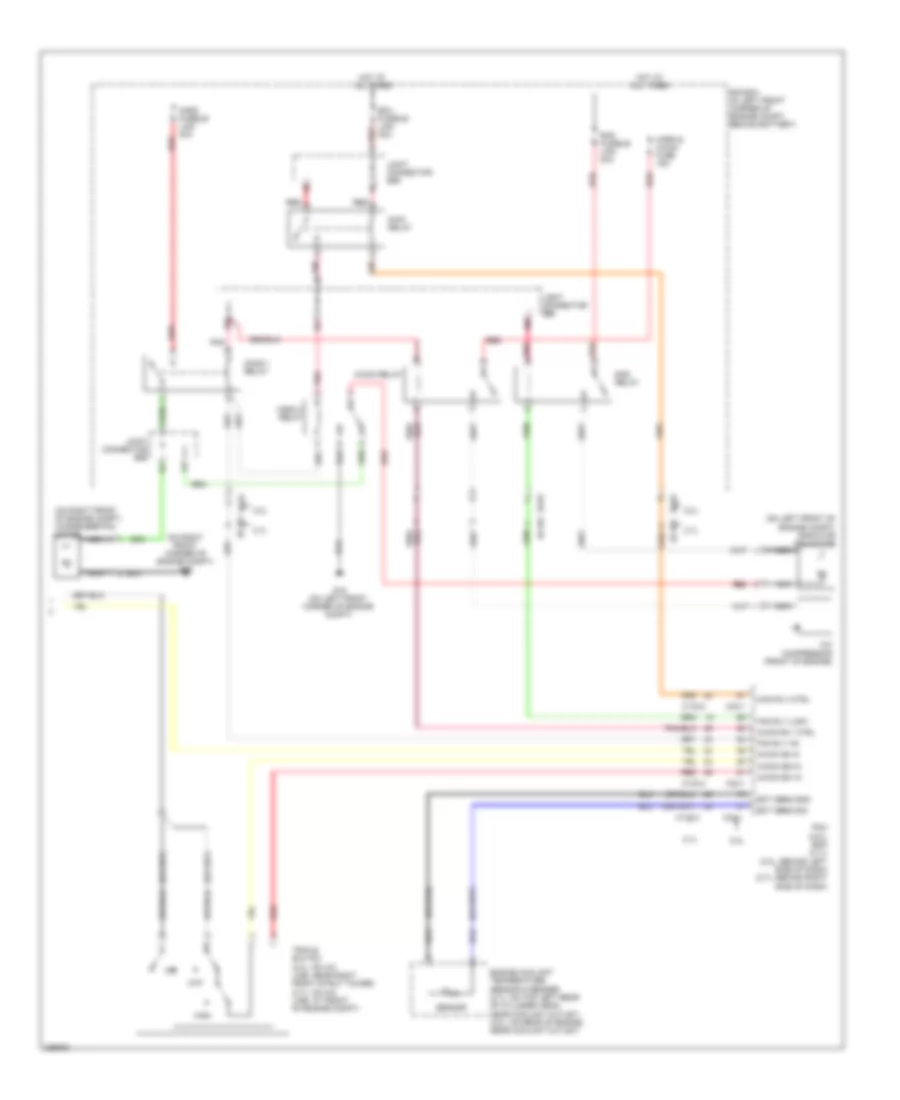
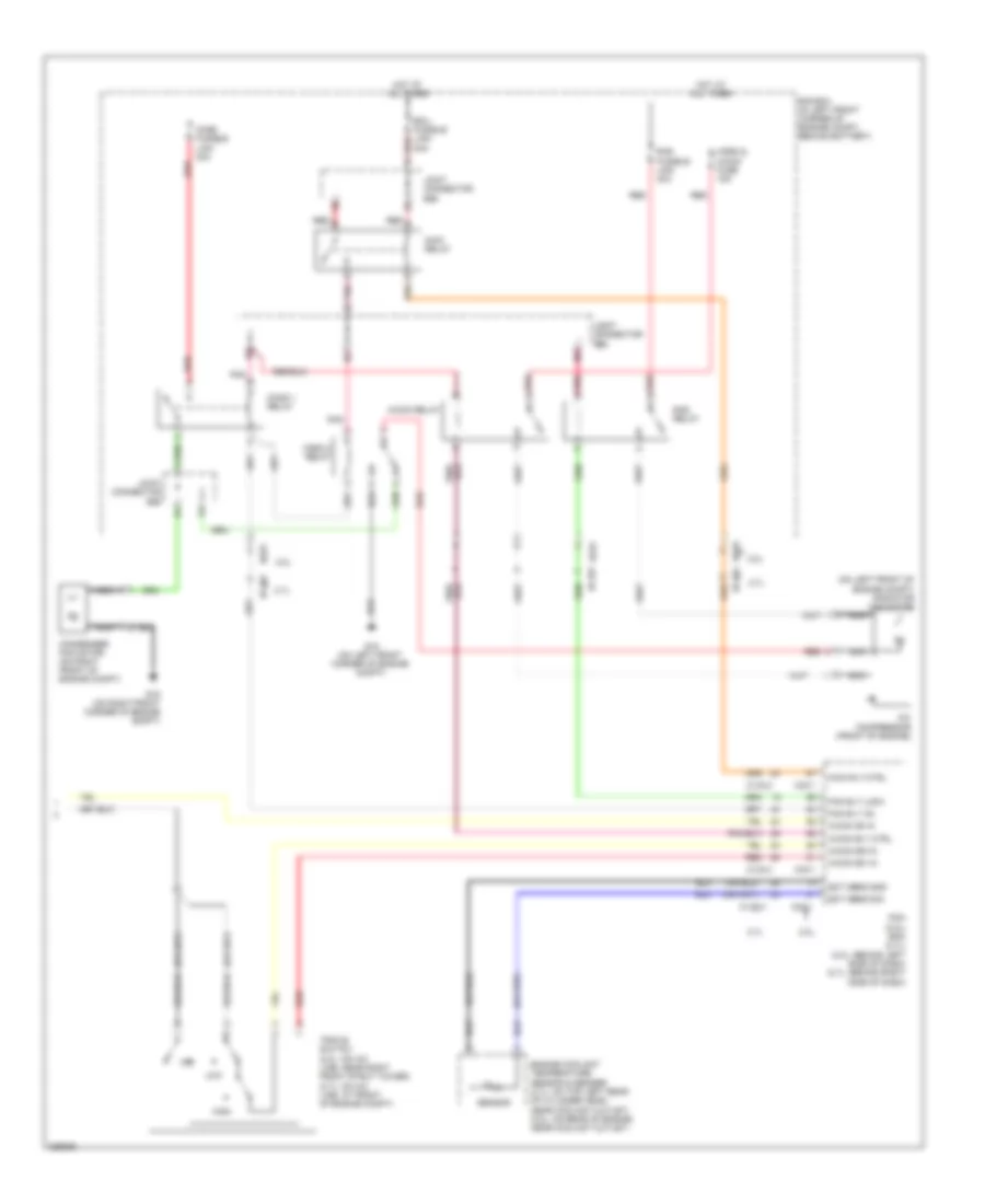
Automatic A/C Wiring Diagram (1 of 2) for Hyundai Tiburon GS 2008

List of elements for Automatic A/C Wiring Diagram (1 of 2) for Hyundai Tiburon GS 2008:
- (beside blower motor, below right side of dash) blower relay
- (left front of engine compt) aqs sensor
- (left side of dash) j/c m36
- (on left front corner of engine compt) g15
- A/c control module (below center of dash, forward of shift lever)
- A/c output
- A/c select sig
- A/con fuse 10a
- Amb sig
- Ambient temperature sensor (behind center of front bumper)
- Aqs sig
- Bcm-ce
- Bcm-im
- Bcm-km
- Blend door actuator (behind right center of dash)
- Blower fusible link 30a
- Blower motor (under right side of dash)
- Blower rly on in
- Body control module box (behind left side of dash)
- Cool actuator
- Cruise control system
- Def actuator
- Defogger
- Defogger ind
- Defogger sw
- E/r box (in left front corner of engine compt, behind battery)
- Fe (field effect) transistor
- Feed back sig
- Fet (drain)
- Fet (gate)
- Fre actuator
- G11 (behind center of dash)
- G12 (behind center of dash)
- Gnd
- Hot at all times
- Hot in on
- Ign fuse 10a
- Ill +
- Ill -
- Intake actuator (behind upper right side of dash)
- Interior lights system
- J/c e56
- Joint connector m35 (left side of dash)
- M19-1
- M19-2
- Memory pwr
- Nca
- On input
- Photo sens gnd
- Photo sensor (on top left side of dash, near defroster vent)
- Pnk
- Power connector
- Rec actuator
- Red
- Room lp fuse 10a
- Sens gnd
- Sens pwr (5v)
- Sens sig
- System
- Temperature actuator (behind lower right center of dash)
- Thermostatic switch (behind right center of dash)
- Vehicle speed sig
- Vent actuator
- Warm actuator
- Water temperature sensor
- Wts +
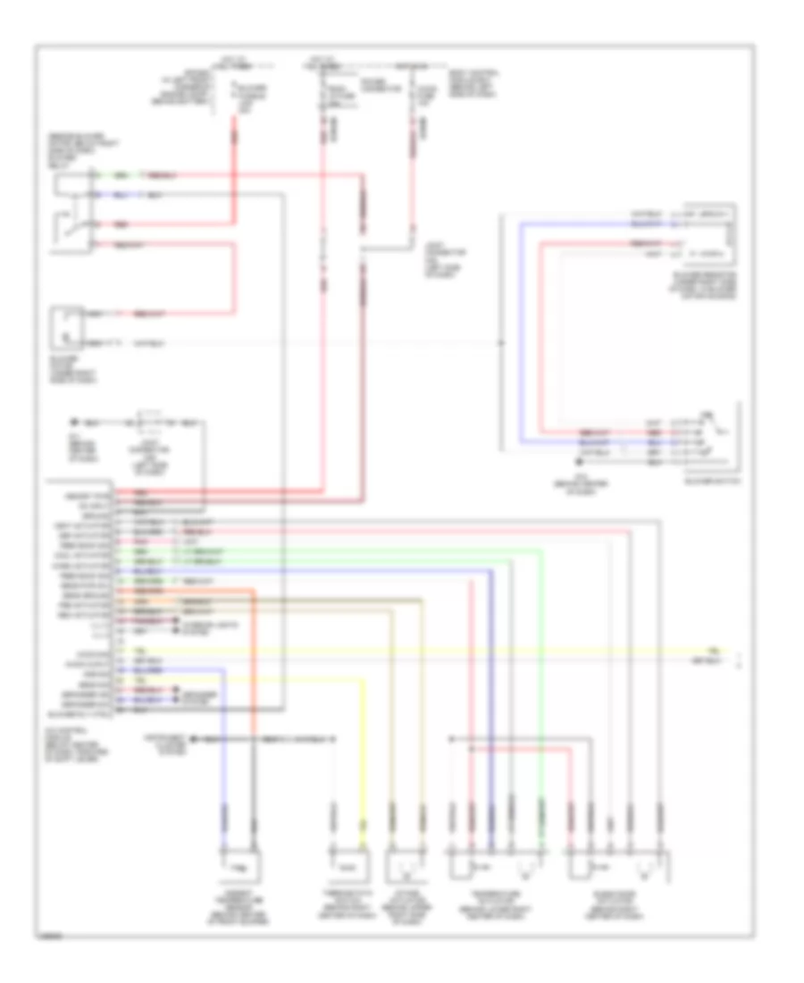
Automatic A/C Wiring Diagram (2 of 2) for Hyundai Tiburon GS 2008
List of elements for Automatic A/C Wiring Diagram (2 of 2) for Hyundai Tiburon GS 2008:
- (on left front of engine compt) radiator fan motor
- (on right front corner of engine compt) g16
- (on right front of engine compt) condenser fan motor
- 2.0l
- 2.7l
- A/c compressor (front of engine)
- A/con on in
- A/con relay
- A/con rly ctrl
- A/con sig in
- A/con sw in
- C133-2
- C133-3
- C133-4
- C33-1
- Cond 1 relay
- Cond 2 relay
- Cond fusible link 30a
- E/r box (in left front corner of engine compt, behind battery)
- Ec01
- Ec02
- Ec101
- Ec102
- Ect sens gnd
- Ect sens sig
- Ecu fusible link 30a
- Engine coolant temperature sensor & sender (2.7l: on top left rear of cylinder head, near coolant outlet) (2.0l: on rear of engine, near coolant outlet)
- Fan rly (hi)
- Fan rly (low)
- G15 (on left front corner of engine compt)
- High
- Horn & a/con fuse 15a
- Hot at all times
- Joint connector e56
- Low
- Main relay
- Main rly ctrl
- Mid
- Nca
- Pcm (2.0l) ecm (2.7l) (2.0l: behind left side of dash) (2.7l: behind right side of dash)
- Pnk
- Rad fusible link 30a
- Rad relay
- Red
- Sensor
- Triple switch (2.0l: on a/c line, near right front strut tower) (2.7l: on a/c line, at front of engine compt)
Manual A/C Wiring Diagram (1 of 2) for Hyundai Tiburon GS 2008
List of elements for Manual A/C Wiring Diagram (1 of 2) for Hyundai Tiburon GS 2008:
- (beside blower motor, below right side of dash) blower relay
- A/c control module (below center of dash, forward of shift lever)
- A/con fuse 10a
- A/con ouput
- A/con sig
- Amb sig
- Ambient temperature sensor (behind center of front bumper)
- Bcm-im
- Bcm-km
- Blend door actuator (behind right center of dash)
- Blower fusible link 30a
- Blower motor (under right side of dash)
- Blower resistor (under right side of dash, in blower motor housing)
- Blower rly ctrl
- Blower switch
- Body control module box (behind left side of dash)
- Cool actuator
- Def actuator
- Defogger ind
- Defogger sw
- Defogger system
- E/r box (in left front corner of engine compt, behind battery)
- Feed back sig
- Fre actuator
- G11 (behind center of dash)
- G12 (behind center of dash)
- Ground
- Hot at all times
- Hot in on
- Iii
- Iiii
- Ill (+)
- Ill (-)
- Instrument cluster system
- Intake actuator (behind upper right side of dash)
- Interior lights system
- Joint connector m35 (left side of dash)
- Joint connector m36 (left side of dash)
- Memory pwr
- Nca
- Off
- On input
- Pnk
- Power connector
- Rec actuator
- Red
- Room lp fuse 10a
- Sens ground
- Sens pwr (5v)
- Sens sig
- Temperature actuator (behind lower right center of dash)
- Thermostatic switch (behind right center of dash)
- Vent actuator
- Warm actuator
Manual A/C Wiring Diagram (2 of 2) for Hyundai Tiburon GS 2008
List of elements for Manual A/C Wiring Diagram (2 of 2) for Hyundai Tiburon GS 2008:
- (on left front of engine compt) radiator fan motor
- 2.0l
- 2.7l
- 30a
- A/c compressor (front of engine)
- A/con on in
- A/con relay
- A/con rly ctrl
- A/con sig in
- A/con sw in
- C133-2
- C133-3
- C133-4
- C33-1
- Cond 1 relay
- Cond 2 relay
- Cond fusible link 30a
- Condenser fan motor (on right front of engine compt)
- E/r box (in left front corner of engine compt, behind battery)
- Ec01
- Ec02
- Ec101
- Ec102
- Ect sens gnd
- Ect sens sig
- Ecu fusible link red
- Engine coolant temperature sensor & sender (2.7l: on top left rear of cylinder head, near coolant outlet) (2.0l: on rear of engine, near coolant outlet)
- Fan rly (hi)
- Fan rly (low)
- G15 (on left front corner of engine compt)
- G16 (on right front corner of engine compt)
- High
- Horn & a/con fuse 15a
- Hot at all times
- Joint connector e56
- Low
- Main relay
- Main rly ctrl
- Mid
- Nca
- Pcm (2.0l) ecm (2.7l) (2.0l: behind left side of dash) (2.7l: behind right side of dash)
- Pnk
- Rad fusible link 30a
- Rad relay
- Red
- Sensor
- Triple switch (2.0l: on a/c line, near right front strut tower) (2.7l: on a/c line, at front of engine compt)