AIR CONDITIONING
Air Conditioning Wiring Diagrams for Isuzu Trooper LS 1998
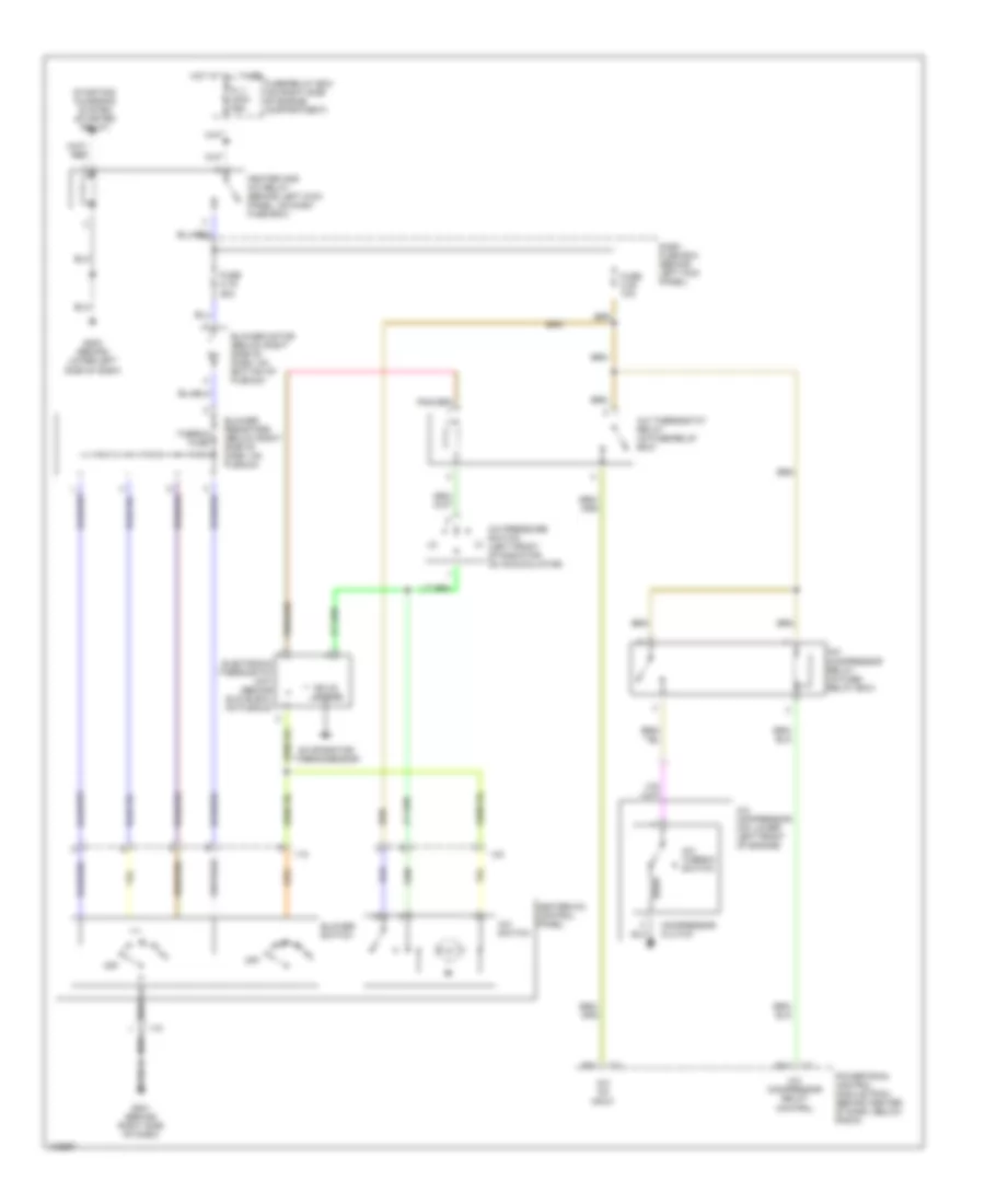
List of elements for Air Conditioning Wiring Diagrams for Isuzu Trooper LS 1998:
- A/c compressor (on lower left front of engine)
- A/c compressor relay (in fuse/ relay box)
- A/c compressor relay control
- A/c on input
- A/c pressure switch (left front of radiator, on accumulator)
- A/c switch
- A/c thermo switch
- A/c thermostat relay (in fuse/relay box)
- B14
- Blower motor (below right side of dash, on bottom of plenum)
- Blower resistors (below right side of dash, on plenum)
- Blower switch
- C-1
- C-3
- Compressor clutch
- Dash fuse box (behind left kick panel)
- E15
- Electronic thermostat unit (behind glove box, on plenum)
- Evaporator thermosensor
- Fl-1 main 80a
- Fuse c-19 25a
- Fuse c-20 10a
- Fuse/relay box (on right side of engine compartment)
- G201 (behind right side of dash)
- G202 (behind lower left side of dash)
- Heater and a/c relay (behind left kick panel, on dash fuse box)
- Heater-a/c control panel
- Hot at all times
- I-18
- I-23
- Off
- Powertrain control module (pcm) (behind center of dash, below radio)
- Solid state
- Starting/ charging system (starter relay)
- Thermo fuse
 English