AIR CONDITIONING
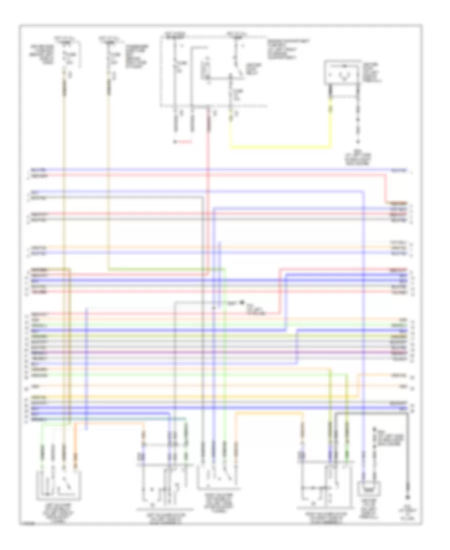
Automatic A/C Wiring Diagram (1 of 3) for Jaguar XKR 2006

List of elements for Automatic A/C Wiring Diagram (1 of 3) for Jaguar XKR 2006:
- (a left front of eng compt) lf2
- 80a
- Ac1
- Ac2
- Air conditioning compressor clutch
- Air conditioning compressor clutch relay (at left rear of engine compartment)
- Air conditioning control module (on right side of hvac assembly)
- Air conditioning pressure sensor (on high pressure refrigerant line)
- Cooling fan module
- Cooling fans fuse box
- Defogger system
- Em19
- Em80
- Engine control module (at right rear of engine compartment, in control module enclosure)
- Engine management fuse box (at right rear of engine compartment, in control module enclosure)
- Fc25
- Fc26
- Fuse 10a
- Hot at all times
- Hot w/ems control relay energized
- Input
- Left blower air intake (at left side of hvac unit)
- Left cooling fan
- Lf15
- Lf35
- Lf36
- Major instrument pack
- Nca
- Output
- Output output
- Red
- Right blower air intake (at right side of hvac unit)
- Right cooling fan
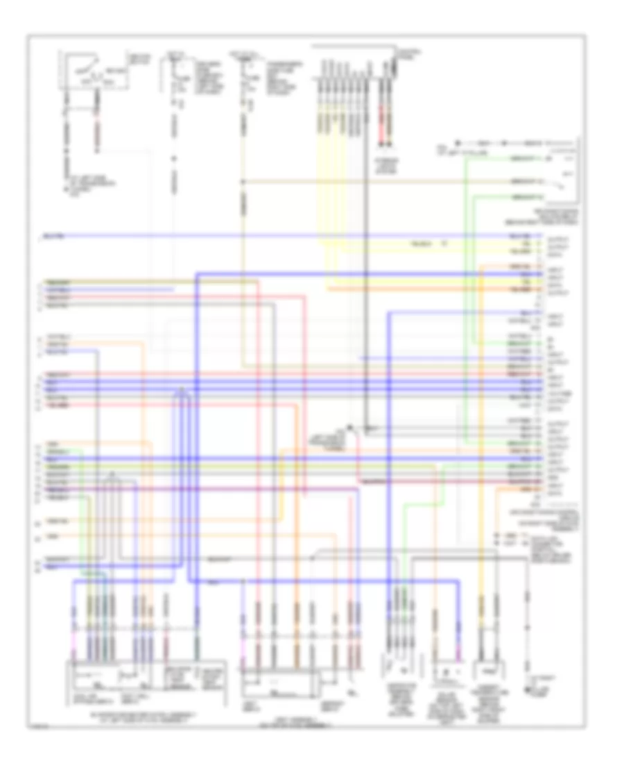
Automatic A/C Wiring Diagram (2 of 3) for Jaguar XKR 2006
List of elements for Automatic A/C Wiring Diagram (2 of 3) for Jaguar XKR 2006:
- Driver side fuse box (behind left side of dash)
- Em2 (at left side of eng compt enclosure)
- Engine compartment fuse box (at left front of engine compartment)
- Fc2 (at right "a" pillar)
- Fc21
- Fc4 (at left "a" pillar)
- Fc6
- Fuse 10a
- Fuse 20a
- Fuse 5a
- Heater pump (on left side of firewall)
- Heater pump relay
- Heater valve (on left side of firewall)
- Hot at all times
- Hot in run or start
- Left blower motor (on left side of hvac assembly)
- Left blower motor relay (on left side of drive shaft tunnel)
- Lf5
- Lf7
- Lf8
- Nca
- Passenger side fuse box (behind right side of dash)
- Right blower motor (on right side of hvac assembly)
- Right blower motor relay (on left side of drive shaft tunnel)
Automatic A/C Wiring Diagram (3 of 3) for Jaguar XKR 2006
List of elements for Automatic A/C Wiring Diagram (3 of 3) for Jaguar XKR 2006:
- (at left side of transmission tunnel) fc3
- (at right "a" pillar) fc2br
- Ac3
- Ac4
- Acc
- Air conditioning control module (on right side of hvac assembly)
- Air conditioning isolate relay (behind right side of dash)
- Ambient temperature sensor (behind right front side of bumper)
- Aspirator assembly (behind driver's knee bolster)
- Clock
- Control panel
- Cool air bypass servo
- Data
- Data link connector (partial) (below driver side fuse box)
- Defrost servo
- Dimmer
- Driver's side fuse box (behind left side of dash)
- Evapor- ator temp sensor
- Evaporator/heater matrix assembly (at left side of hvac assembly)
- Fc20
- Fc3 (left side of transmission tunnel)
- Fc4 (at left "a" pillar)
- Fc6
- Foot well servo
- Fuse 10a
- Gnd
- Heater matrix temp sensor
- Hot at all times
- Hot in run
- Ignition switch
- Illum
- Input
- Interior lights system
- Nca
- Off
- Output
- Passenger's side fuse box (behind right side of dash)
- Red
- Run
- Solar sensor (on top left side of dash on defroster vent)
- Start
- Vent assembly (on top of hvac assembly)
- Vent servo
- Voltage