AIR CONDITIONING
Automatic A/C Wiring Diagram for Jeep Grand Cherokee Limited 2001

List of elements for Automatic A/C Wiring Diagram for Jeep Grand Cherokee Limited 2001:
- (4.0l)
- (4.7l)
- (at bottom of steering column)
- (at right front corner of engine compartment, next to battery) power distribution center
- (between troughs in right engine compartment)
- (in center spline trough side) s316
- (near air bag control module) g302
- (near breakout for front power outlet) s201
- (near power distribution center) g101
- (right rear of engine) g117
- 4.0l
- 4.7l
- A/c comp rly ctrl
- A/c compressor clutch
- A/c compressor clutch relay
- A/c high pressure switch (on discharge line block fitting, near compressor)
- A/c low pressure switch (on top of accumulator)
- A/c press signal
- A/c switch signal
- A16
- Automatic zone control module
- Battery
- Blower motor (on passenger side end of heater-a/c housing)
- Blower motor controller (on heater-a/c housing, inboard of blower motor)
- Blower motor ctrl
- Blower mtr ctrl
- Blwr mtr high dr
- Body control module (on left end of dash, attached to junction block)
- C100
- C102
- C103
- C13
- C15
- C18
- C21
- C23
- C24
- C32
- C33
- C35
- C56
- C94
- C95
- C96
- D25
- Defogger relay out
- Defogger sw sense
- Defogger system
- Diagnostic junction port
- Dr blend door dr
- Dr blnd door driver
- Driver blend door motor/actuator (on heater-a/c housing)
- Driver blnd door driver
- F22
- Fuse 15a
- Fuse 20 10a
- Fuse 21 10a
- Fuse 40a
- Fuse 7 10a
- Ground
- Hot at all times
- Hot in run
- Hot in run or start
- Ignition
- Junction block (behind left side of dash)
- Mode door driver
- Mode door motor/actuator (on heater-a/c housing)
- Panel lamps driver
- Pass blend door dr
- Pass blend door driver
- Passenger blend door motor/actuator (on heater-a/c housing)
- Pci bus
- Pnk
- Power distribution center (at right front corner of engine compartment, next to battery)
- Powertrain control module (on right side of firewall)
- Radiator fan motor (behind radiator)
- Radiator fan relay (behind bumper fascia, below right headlamp)
- Radiator fan relay ctrl
- Recirc door driver
- Recirculation door motor/actuator (on heater-a/c housing)
- Red
- Relay ctrl
- Relay output
- S103 (4.0l: near breakout for oxygen sensor 1/1 upstream) (4.7l: near breakout for engine oil pressure switch)
- S132
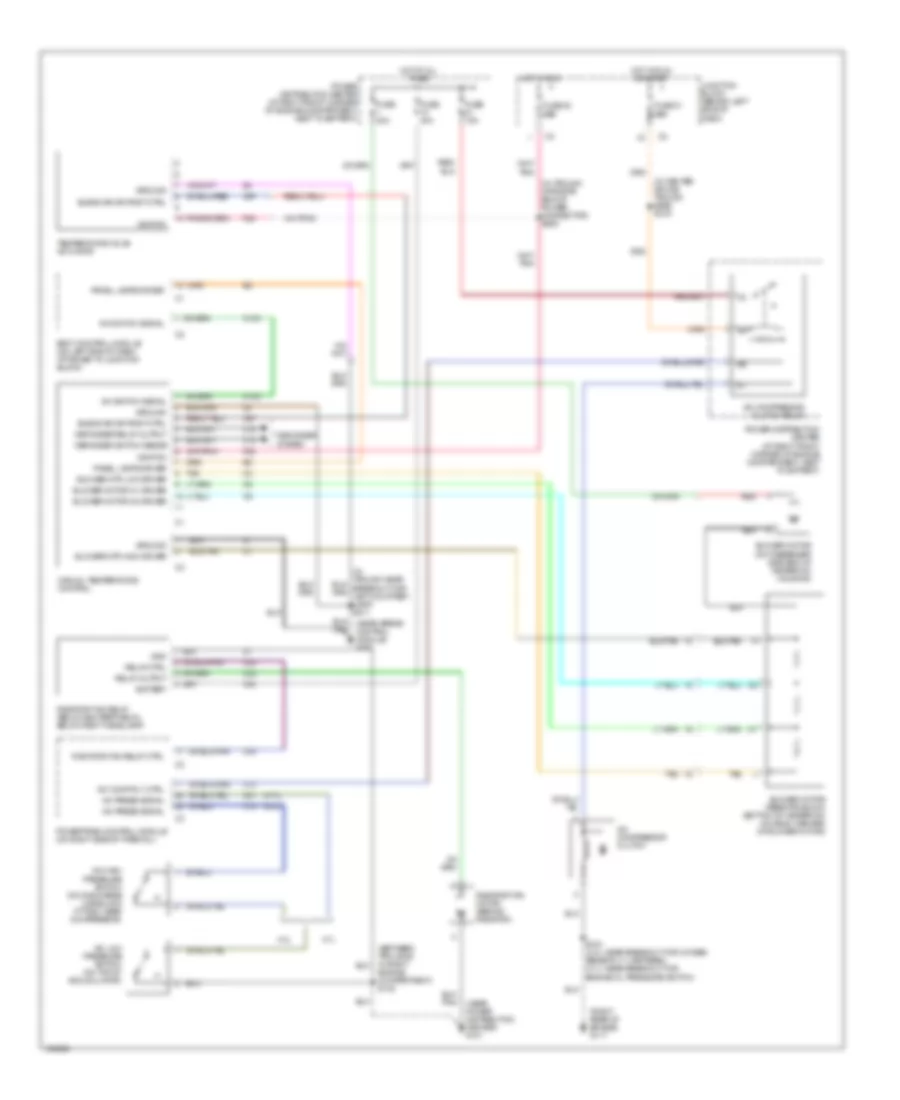
Manual A/C Wiring Diagram for Jeep Grand Cherokee Limited 2001
List of elements for Manual A/C Wiring Diagram for Jeep Grand Cherokee Limited 2001:
- (4.0l)
- (4.7l)
- (between troughs in right engine compartment) s132
- (in center spline trough side) s316
- (in trough opposite end of power connector) s206
- (near power distribution center) g101
- (right rear of engine) g117
- 4.0l
- 4.7l
- A/c comp rly ctrl
- A/c compressor clutch
- A/c compressor clutch relay
- A/c high pressure switch (on discharge line block fitting, near compressor)
- A/c low pressure switch (on top of accumulator)
- A/c press signal
- A/c switch signal
- A16
- Battery
- Blend air dr posit ctrl
- Blower motor (on passenger side end of heater-a/c housing)
- Blower motor m1 driver
- Blower motor m2 driver
- Blower motor resistor block (bottom of heater-a/c housing, inboard of blower motor)
- Blower mtr high driver
- Blower mtr low driver
- Body control module (on left end of dash, attached to junction block)
- C103
- C13
- C15
- C18
- C21
- C23
- C24
- C67
- Defogger relay output
- Defogger switch sense
- Defogger system
- F22
- Fuse 15a
- Fuse 20 10a
- Fuse 21 10a
- Fuse 40a
- Gnd
- Ground
- Hot at all times
- Hot in run
- Hot in run or start
- Ignition
- Junction block (behind left side of dash)
- Manual temperature control
- Panel lamps driver
- Power distribution center (at right front corner of engine compartment, next to battery)
- Powertrain control module (on right side of firewall)
- Radiator fan motor (behind radiator)
- Radiator fan relay (below bumper fascia, below right headlamp)
- Radiator fan relay ctrl
- Red
- Relay ctrl
- Relay output
- S103 (4.0l: near breakout for oxygen sensor 1/1 upstream) (4.7l: near breakout for engine oil pressure switch)
- Tan
- Temperature valve actuator