AIR CONDITIONING
Automatic A/C Wiring Diagram (1 of 2) for Mazda 5 Grand Touring 2013

List of elements for Automatic A/C Wiring Diagram (1 of 2) for Mazda 5 Grand Touring 2013:
- (right side of a/c unit) air intake actuator
- 0740-201a
- 0740-201b
- A/c fuse 10a
- A/c mag fuse 10a
- A/c relay
- Blower relay 1
- Blower relay 2
- C-02
- C-05
- C-66
- Climate control unit
- Computer data lines system
- Front blower motor (center of a/c unit)
- Front power mos fet (lower right side of a/c unit)
- Fuse block (right end of dash)
- G02
- G09 (left side of dash)
- Heater 1 fuse 40a
- Heater 2 fuse 30a
- Heater 3 fuse 30a
- Hot at all times
- Hot in on or start
- Interior lights system
- J/c c-44
- J/c g02
- J/c g09
- Magnetic clutch (on a/c compressor)
- Rear blower motor (under center of dash)
- Rear fan switch
- Rear vent actuator (lower front of a/c unit)
- Red
- Relay & fuse block (left rear of engine compt)
- Room fuse 15a
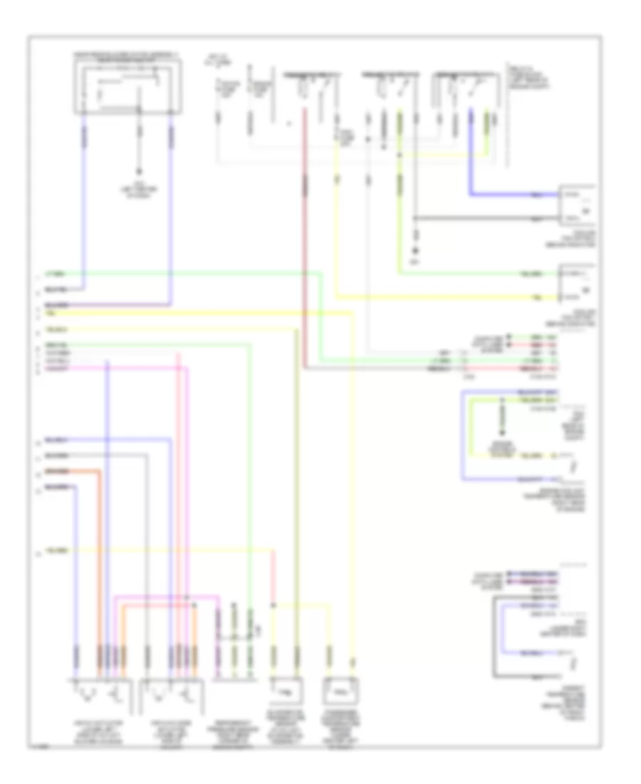
Automatic A/C Wiring Diagram (2 of 2) for Mazda 5 Grand Touring 2013
List of elements for Automatic A/C Wiring Diagram (2 of 2) for Mazda 5 Grand Touring 2013:
- (near rear blower motor assembly) rear power mos fet
- 0140-101a
- 0140-101b
- 0940-101a
- 0940-101f
- 1ai
- 1am
- 2ah
- 2av
- Ad fan fuse 30a
- Air flow mode actuator (lower left side of a/c unit)
- Air mix actuator (lower left side of a/c unit blower housing)
- Ambient temperature sensor (behind center of front fascia)
- Bcm (under right center of dash)
- C-02
- C-05
- Computer data lines system
- Cooling fan motor 1 (behind radiator)
- Cooling fan motor 2 (behind radiator)
- Cooling fan relay 1
- Cooling fan relay 2
- Cooling fan relay 3
- Eng+b fuse 10a
- Engine controls system
- Engine coolant temperature sensor (right rear of engine)
- Evaporator temperature sensor (in a/c unit evaporator assembly)
- Fan1 fuse 30a
- G01
- G12 (left center of dash)
- Hot at all times
- Passenger compartment temperature sensor (under center left of dash)
- Pcm (left rear of engine compt)
- Red
- Refrigerant pressure sensor (right rear corner of engine compt)
- Relay & fuse block (left rear of engine compt)