AIR CONDITIONING
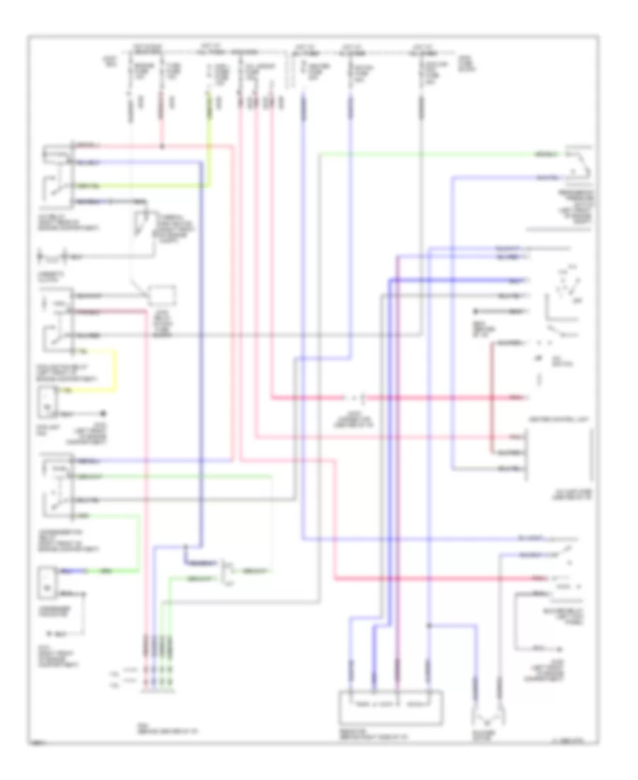
A/C Wiring Diagram, with Logical Mode Control for Mazda Protege ES 1997

List of elements for A/C Wiring Diagram, with Logical Mode Control for Mazda Protege ES 1997:
A/C Wiring Diagram, without Logical Mode Control for Mazda Protege ES 1997
List of elements for A/C Wiring Diagram, without Logical Mode Control for Mazda Protege ES 1997:
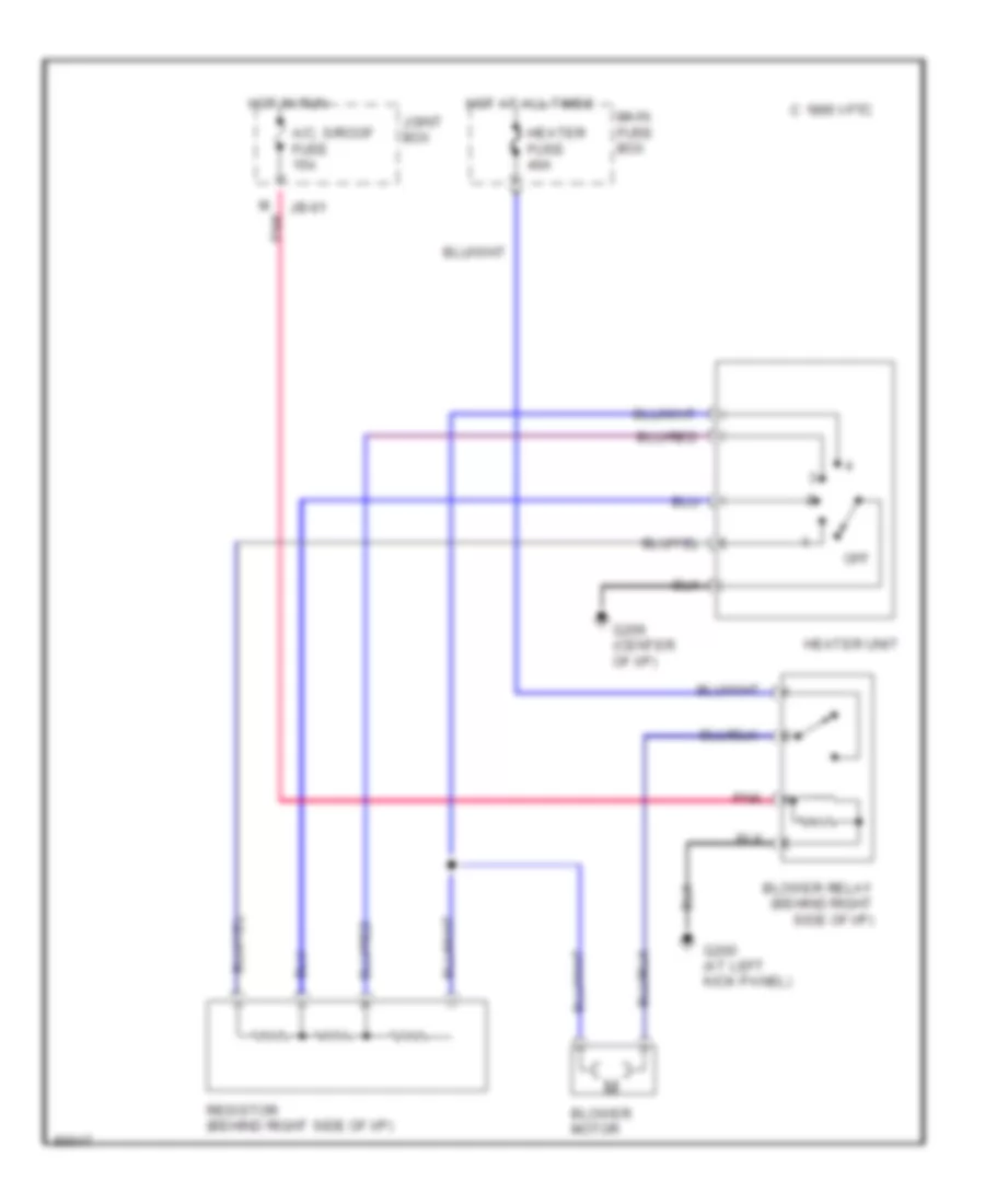
Heater Wiring Diagram for Mazda Protege ES 1997
List of elements for Heater Wiring Diagram for Mazda Protege ES 1997: