AIR CONDITIONING
Automatic A/C Wiring Diagram, with Thermotronic (1 of 3) for Mercedes-Benz C300 4Matic 2008

List of elements for Automatic A/C Wiring Diagram, with Thermotronic (1 of 3) for Mercedes-Benz C300 4Matic 2008:
- (+)
- (-)
- +12v
- 12v
- Ac housing
- Air recirculation mode button
- Automatic air conditioning control & operating unit
- Blower motor
- Blower regulator
- Can b h
- Can b l
- Computer data lines system
- Cp2
- Data
- Data fond
- Evaporator temperature sensor (under right side of dash)
- Front electrical prefuse box (at right rear of engine compt)
- Fuse 100a
- Fuse 40a
- Fuse 7.5a
- Fuse 80a
- Gnd
- Hot at all times
- Hot w/ quiescent current cutout relay energized
- Interior fuse box (behind left end of dash)
- Left front footwell air outlet temperature sensor (behind left side of dash)
- Left side air outlet temperature sensor (behind left side of dash)
- Lin b8
- Ntc
- Rear blower motor
- Rear footwell air outlet temperature sensor
- Rear window heater button
- Red
- Right front footwell air outlet temperature sensor (behind right side of dash)
- Right side air outlet temperature sensor (behind right side of dash)
- Sig
- Sun sensor (top center of dash)
- W15/5 (left front footwell)
- W15/7 (right front footwell)
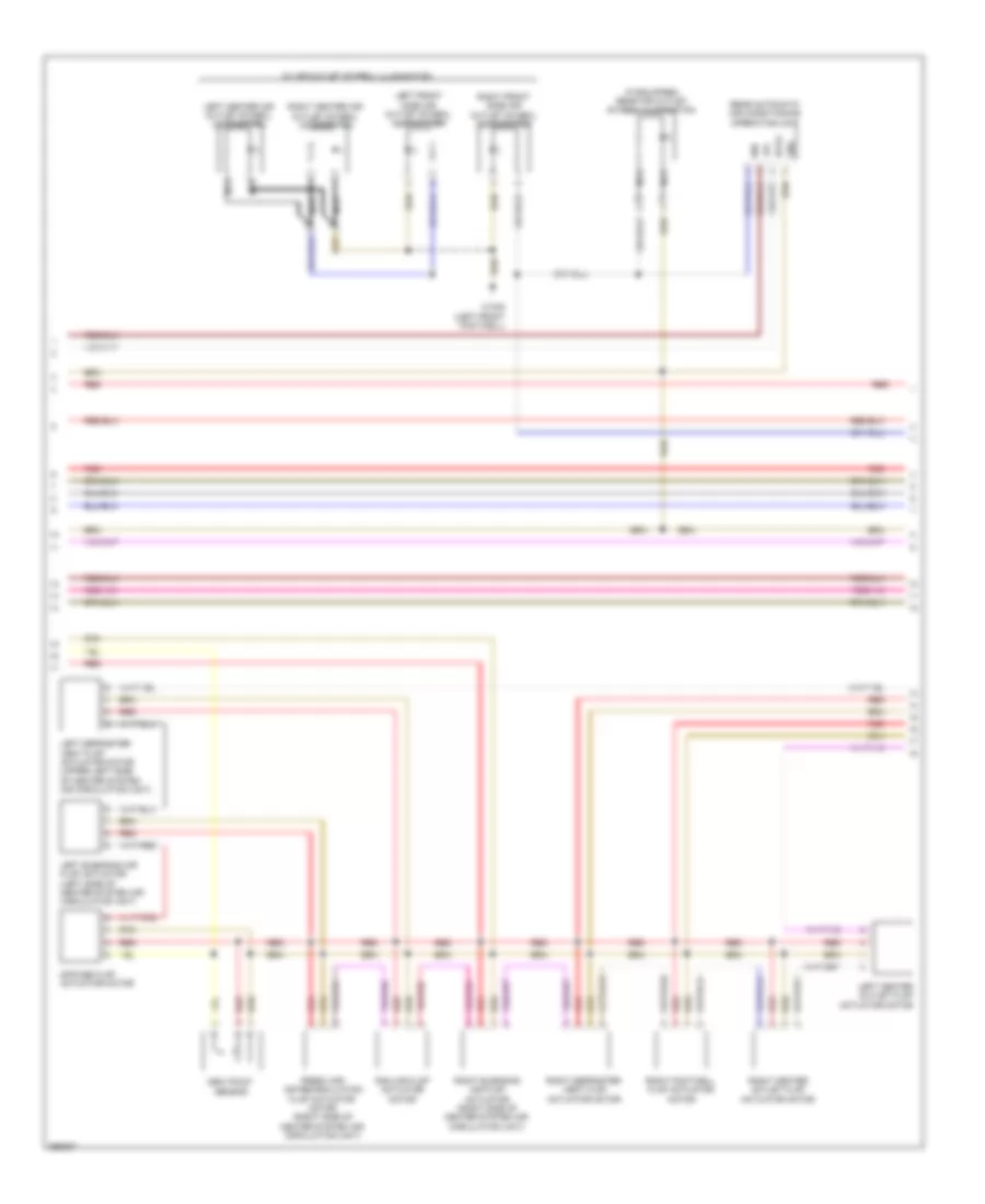
Automatic A/C Wiring Diagram, with Thermotronic (2 of 3) for Mercedes-Benz C300 4Matic 2008
List of elements for Automatic A/C Wiring Diagram, with Thermotronic (2 of 3) for Mercedes-Benz C300 4Matic 2008:
- (if equipped) rear air outlet symbol illumination
- 12v
- 58d
- Data
- Dew point sensor
- Diffuse flap actuator motor
- Fresh air/ air recirculation flap actuator motor (right side of heater system air circulation unit)
- Gnd
- Left blending air flap actuator (left side of heater system air circulation unit)
- Left center air outlet symbol illumination
- Left center outlet flap actuator motor
- Left defroster vent flap actuator motor (upper left side of heater system air circulation unit)
- Left front side air outlet symbol illumination
- Nca
- Ram air flap actuator motor
- Rear automatic air conditioning operating unit
- Red
- Right blending air flap actuator (right side of heater system air circulation unit)
- Right center air outlet symbol illumination
- Right center outlet flap actuator motor
- Right defroster vent flap actuator motor
- Right footwell flap actuator motor
- Right front side air outlet symbol illumination
- W/ air outlet symbol illumination
- W15/5 (left front footwell)
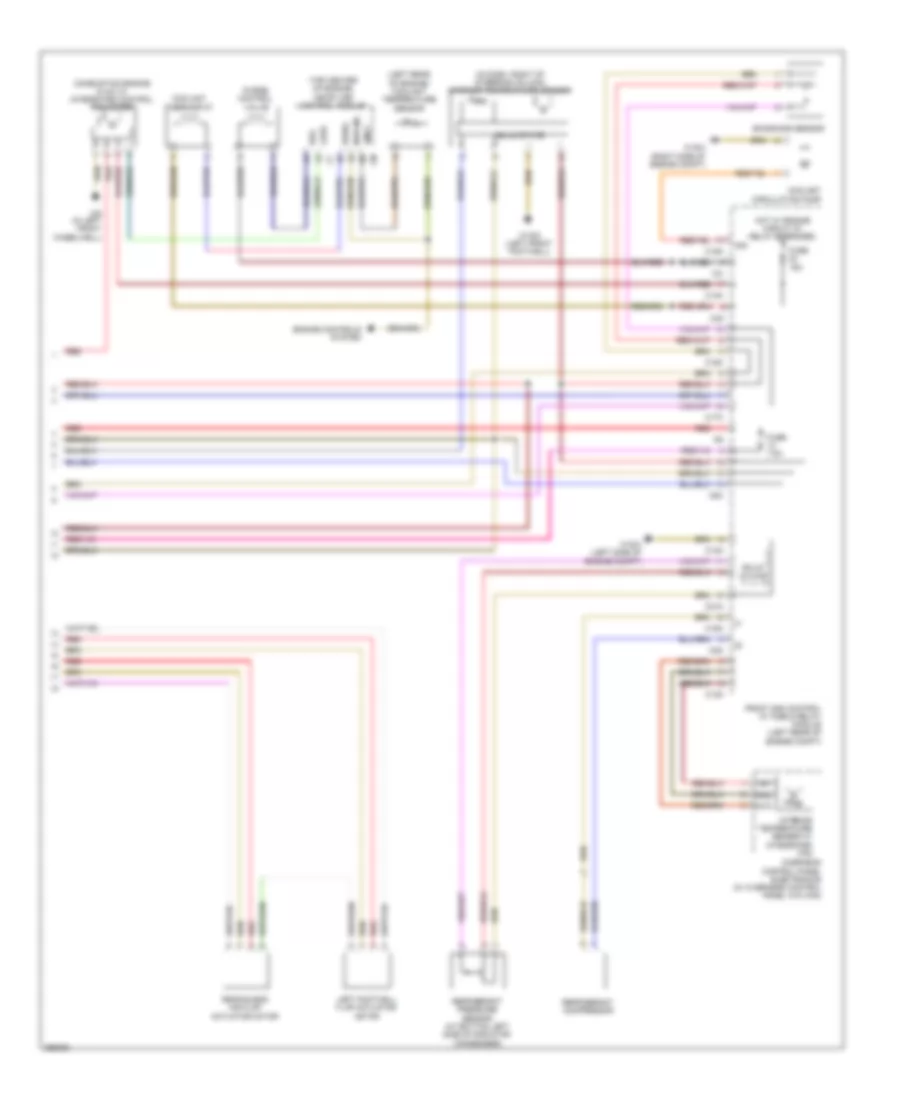
Automatic A/C Wiring Diagram, with Thermotronic (3 of 3) for Mercedes-Benz C300 4Matic 2008
List of elements for Automatic A/C Wiring Diagram, with Thermotronic (3 of 3) for Mercedes-Benz C300 4Matic 2008:
- (in dash, right of steering column) interior temperature sensor
- (left rear of engine) coolant temperature sensor
- (top center of engine) me-sfi (me) control module
- 12v
- C13d
- C14m
- C17c
- C18m
- C21m
- C3m
- C4i
- C5c
- Combustion engine & a/c w/ integrated control fan motor
- Coolant circulation pump
- Coolant thermostat
- Emissions sensor
- Engine controls system
- Front sam control w/ fuse & relay module (left rear of engine compt)
- Fuse 15a
- Fuse 7.5a
- Gnd
- Hot w/ engine circuit 87 relay energized
- Interior temperature sensor w/ integrated fan
- Kwhs
- Left footwell flap actuator motor
- Lues
- Ntc
- Nwg m2
- Overhead control panel electronics (w/ overhead control panel w/o can)
- Purge control valve
- Rear blend air flap actuator motor
- Red
- Refrigerant compressor
- Refrigerant pressure sensor (at bottom left side of radiator condenser)
- Reg
- Sig
- Solid state
- Tmot
- W15/5 (left front footwell)
- W16/3 (left side of engine compt)
- W16/4 (right side of engine compt)
- W9 (in left front wheelwell)
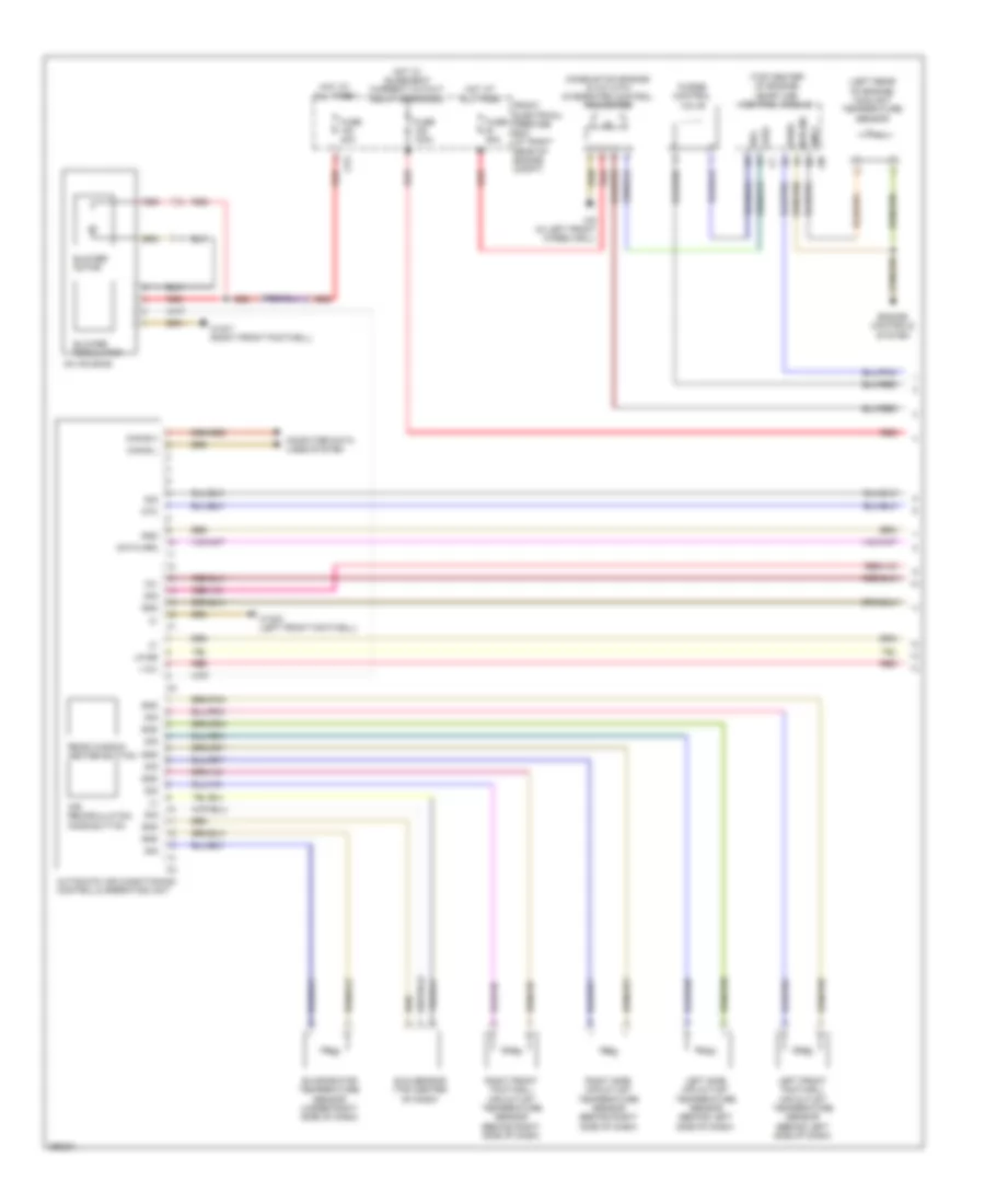
Automatic A/C Wiring Diagram, without Thermotronic (1 of 2) for Mercedes-Benz C300 4Matic 2008
List of elements for Automatic A/C Wiring Diagram, without Thermotronic (1 of 2) for Mercedes-Benz C300 4Matic 2008:
- (+)
- (left rear of engine) coolant temperature sensor
- (top center of engine) me-sfi (me) control module
- +12v
- 12v
- 30g
- Ac housing
- Air recirculation mode button
- Automatic air conditioning control & operating unit
- Blower motor
- Blower regulator
- Can-b h
- Can-b l
- Combustion engine & a/c with integrated control fan motor
- Computer data lines system
- Cp2
- Data mrm
- Engine controls system
- Evaporator temperature sensor (under right side of dash)
- Front electrical prefuse box (at right rear of engine compt)
- Fuse 100a
- Fuse 40a
- Fuse 80a
- Gnd
- Hot at all times
- Hot w/ quiescent current cutout relay energized
- Kwhs
- Left front footwell air outlet temperature sensor (behind left side of dash)
- Left side air outlet temperature sensor (behind left side of dash)
- Lin b8
- Lues
- Ntc
- Nwg m2
- Purge control valve
- Rear window heater button
- Red
- Reg
- Right front footwell air outlet temperature sensor (behind right side of dash)
- Right side air outlet temperature sensor (behind right side of dash)
- Sig
- Sun sensor (top center of dash)
- Tmot
- W15/5 (left front footwell)
- W15/7 (right front footwell)
- W9 (in left front wheelwell)
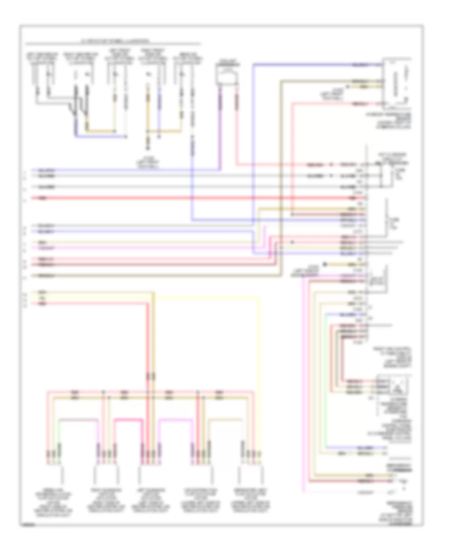
Automatic A/C Wiring Diagram, without Thermotronic (2 of 2) for Mercedes-Benz C300 4Matic 2008
List of elements for Automatic A/C Wiring Diagram, without Thermotronic (2 of 2) for Mercedes-Benz C300 4Matic 2008:
- 12v
- Air distribution flap actuator motor (lower left side of heater system air circulation unit)
- C13d
- C14m
- C17c
- C18m
- C21m
- C3m
- C4i
- Coolant thermostat
- Defroster vent flap actuator motor (upper left side of heater system air circulation unit)
- Fresh air/ air recirculation flap actuator motor (right side of heater system air circulation unit)
- Front sam control w/ fuse & relay module (left rear of engine compt)
- Fuse 15a
- Fuse 7.5a
- Gnd
- Hot w/ engine circuit 87 relay energized
- Interior temperature sensor (in dash, right of steering column)
- Interior temperature sensor w/ integrated fan
- Left blending air flap actuator (left side of heater system air circulation unit)
- Left center air outlet symbol illumination
- Left front side air outlet symbol illumination
- Nca
- Ntc
- Overhead control panel electronics (w/ overhead control panel w/o can)
- Rear air outlet symbol illumination
- Red
- Refrigerant compressor
- Refrigerant pressure sensor (at bottom left side of radiator condenser)
- Right blending air flap actuator (right side of heater system air circulation unit)
- Right center air outlet symbol illumination
- Right front side air outlet symbol illumination
- Solid state
- W/ air outlet symbol illumination
- W15/5 (left front footwell)
- W16/3 (left side of engine compt)