AIR CONDITIONING
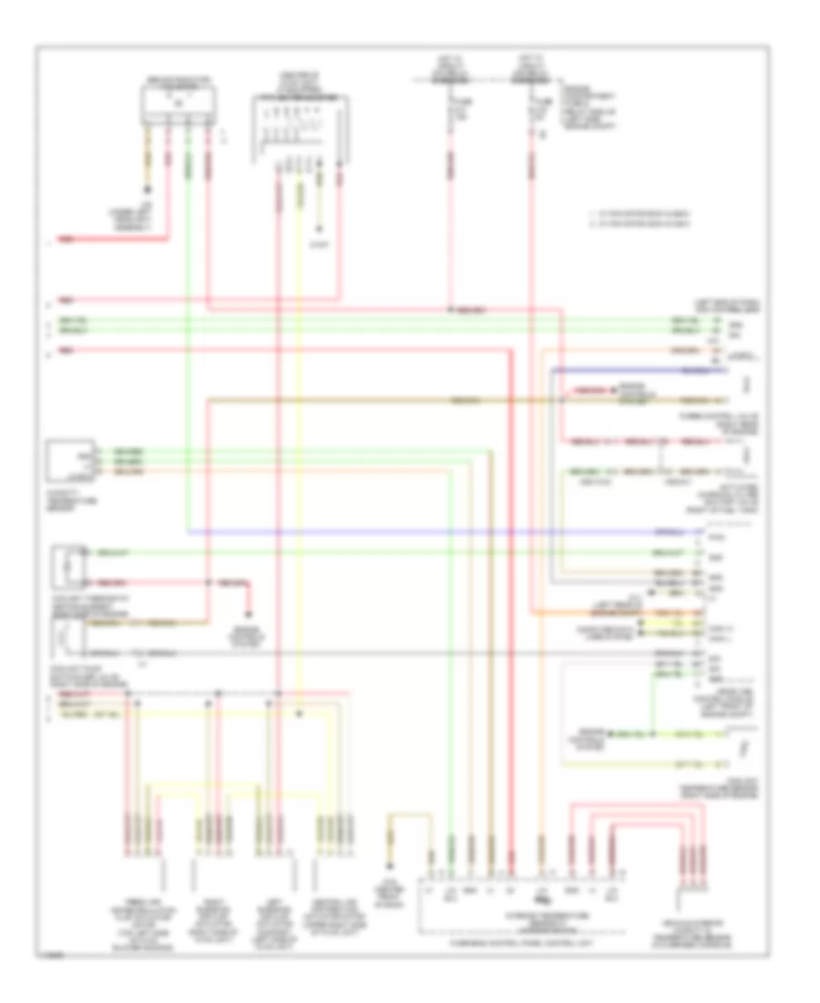
Automatic A/C Wiring Diagram (1 of 2) for Mercedes-Benz CLA250 4Matic 2014

List of elements for Automatic A/C Wiring Diagram (1 of 2) for Mercedes-Benz CLA250 4Matic 2014:
- (+)
- (behind left side of front bumper) outside temperature sensor
- (not used)
- (right rear of engine compt) coolant circulation pump
- (under left front of center console)
- 30g
- 34kd
- Ac housing
- Air quality sensor (right rear of engine compt)
- Air recir- culation mode button
- Automatic air conditioning control & operating unit
- Bf-sig
- Blower motor
- Blower regulator
- Can-b h
- Can-b l
- Central air distribution position detection microswitch (comfort) (bottom right side of hvac unit)
- Computer data lines system
- Defogger system
- Evaporator temperature sensor (lower left side of evaporator)
- F-sig
- Front electrical prefuse box (left side of engine compt)
- Fuse 10a
- Fuse 150a
- Fuse 40a
- Fuse 7.5a
- Fuse 80a
- Gnd
- Hot at all times
- Hot w/ circuit 30g relay energized
- In-b8
- Interior temperature sensor (comfort) (left center of dash)
- Lin b8
- Mk (+)
- Mot
- Nca
- Rear window heater button
- Red
- Refrigerant compressor (lower left front of engine)
- Refrigerant pressure sensor (right front of engine compt)
- Rv (+)
- Rv (-)
- S-sig
- S29
- Sig
- Sun sensor (comfort) (top center front of dash)
- Vehicle interior fuse box (right front footwell)
- W/ magnetic clutch
- W/o magnetic clutch
- W12
- W15/1 (right front footwell)
- W3/1 (right front wheelwell)
- X25/14-c1
- X26-c1
Automatic A/C Wiring Diagram (2 of 2) for Mercedes-Benz CLA250 4Matic 2014
List of elements for Automatic A/C Wiring Diagram (2 of 2) for Mercedes-Benz CLA250 4Matic 2014:
- (+)
- (behind radiator) fan motor
- (center of hvac unit) (if equipped) ptc heater booster
- (left end of dash) sam control unit
- Activated charcoal filter shutoff valve (right of fuel tank)
- Can-i h
- Can-i l
- Central air distribution actuator motor (upper right side of hvac unit)
- Computer data lines system
- Coolant pump switchover valve (right side of engine)
- Coolant temperature sensor (right side of engine)
- Coolant thermostat heating element (right side of engine)
- Engine compartment fuse & relay module (left side engine compt)
- Engine controls system
- Fresh air/ air recirculation flap actuator motor (top left side of hvac blower housing)
- Fuse 15a
- Fuse 5a
- Gnd
- Hot w/ circuit 30g relay energized
- Hot w/ circuit 87m relay energized
- Humidity/ temperature sensor
- Interior temperature sensor w/ integrated fan
- Left blending air flap actuator (comfort) (left side of hvac unit)
- Lin b13
- Me-sfi (me) control module (left front of engine compt)
- Overhead control panel control unit
- Purge control valve (right rear of engine)
- Pwm
- Red
- Right blending air flap actuator (right side of hvac unit)
- Sig
- Uh1
- Vehicle interior humidity & temperature sensor (in overhead console)
- W/ fan motor 300w & 400w
- W/ fan motor 600w & 850w
- W11 (left rear of engine compt)
- W15/7
- W78 (center front of roof)
- W9 (under left headlight assembly)
- X25/13-c2
- X36/2-c1