AIR CONDITIONING
Automatic A/C Wiring Diagram for Mercedes-Benz CLK500 2004
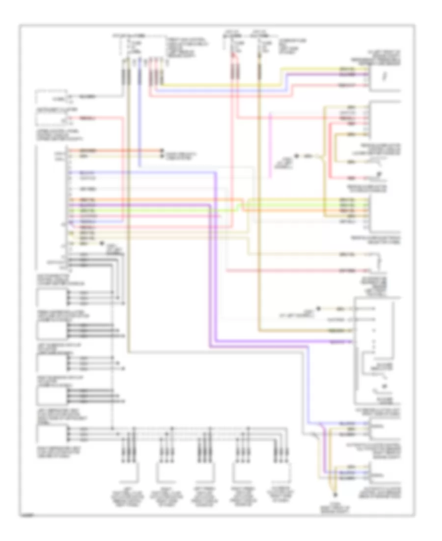
List of elements for Automatic A/C Wiring Diagram for Mercedes-Benz CLK500 2004:
- (in left front of engine compt) refrigerant pressure & temperature sensor
- 12v
- 15 ges.
- A/c recir- culation unit (right side of dash)
- A/c recirculation unit (right side of dash)
- Aac pushbutton control module (lower center console)
- Automatic climate control multifunction sensor (right rear of engine compt)
- Automatic climate control sun sensor (rear of engine hood)
- Blower motor
- Blower regulator
- C15
- C19
- C20
- Can h
- Can l
- Computer data lines system
- Data out
- Evaporator temperature sensor (left front footwell)
- Fresh air/recirculated air flaps actuator motor (under glove box)
- Front sam control module fuse & relay module (left rear of engine compt)
- Fuse 15a
- Fuse 40a
- Fuse 7.5a
- Hot at all times
- Instrument cluster
- Interior fuse box (left side of dash)
- Left footwell flap actuator motor (behind instru- ment panel)
- Left blending air flap actuator (left side of dash)
- Left defroster vent flap actuator motor (right side of instrument panel)
- Left fresh air flap actuator (front middle console)
- Nca
- Rear blower electronic selector wheel
- Rear blower motor (in middle console)
- Rear blower motor control module (lower center console)
- Red
- Right footwell flap actuator motor (right side of dash)
- Right blending air flap actuator (under glove box)
- Right defroster vent flap actuator motor (center of dash)
- Right fresh air flap actuator (front middle console)
- Signal
- Upper control panel control module (upper center cockpit)
- W16/4 (right front of engine compt)
- W28/1 (at left doorsill)
 English