AIR CONDITIONING
Automatic A/C Wiring Diagram (1 of 2) for Mercedes-Benz ML500 2005

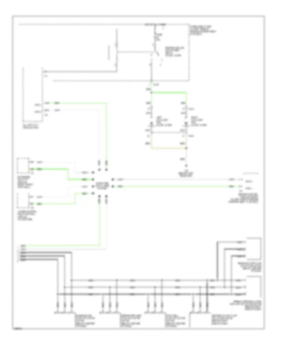
List of elements for Automatic A/C Wiring Diagram (1 of 2) for Mercedes-Benz ML500 2005:
- (behind right kick panel) w29/2
- (below right front seat)
- A/c compressor
- Aac pushbutton control module (behind center of dash)
- C/c
- C/g
- Can h
- Can l
- Center nozzle air stream temperature sensor (below center of dash)
- Computer data lines
- Coolant circulation pump (right rear of engine compt)
- Data link connector
- Defogger system
- Evaporator temperature sensor (behind right side of dash, in evaporator)
- Front footwell airstream temperature sensor (below center of dash)
- Fuse & relay box (in left side of engine compartment, in "e" box)
- Fuse 15a
- Fuse 20a
- Fuse 40a
- Heating systems recirculation unit (below right side of dash)
- Hot at all times
- Hot in run or start
- Interior lights system
- Module box blower motor (in left side of engine compartment)
- Mr/e
- Nca
- Pnk
- Rear air distribution flap actuator motor (below rear center console)
- Rear airstream temperature sensor (below rear of center console)
- Rear blower motor (below rear center console)
- Rear ventilation electronic blower controller (below center console)
- Red
- Refrigerant pressure & temperature sensor (left front of engine compt)
- Right front footwell fuse & relay box (behind right kick panel)
- Sun sensor (top of dash)
- W16/4 (right side of firewall)
- W19
- W29/2 (behind right kick panel)
Automatic A/C Wiring Diagram (2 of 2) for Mercedes-Benz ML500 2005
List of elements for Automatic A/C Wiring Diagram (2 of 2) for Mercedes-Benz ML500 2005:
- A12
- All activity module (aam)
- B12
- Blending air flap actuator motor (below center of dash)
- Can h
- Can l
- Center outlet flap actuator motor (behind right side of dash)
- Computer data lines system
- Defroster vent flap actuator motor (below center of dash)
- Engine control module (me-sfi) (in left side of engine compartment, in "e" box)
- Engine cooling fan stage 1 relay (ml320, ml350)
- Extended activity module (right front footwell)
- Footwell flap actuator motor (below center of dash)
- Fresh & recirculated air flap actuator motor (behind right side of dash)
- Fuse & relay box (in left side of engine compartment, in "e" box)
- Fuse 40a
- Hot at all times
- Left auxiliary fan (ml320, ml350)
- Lower control field control module (at shifter)
- M4x1
- Ml/b
- Nca
- Rear shutoff flap actuator motor (below center of dash)
- Right auxiliary fan (ml320, ml350)
- W9 (behind left headlamp)