AIR CONDITIONING
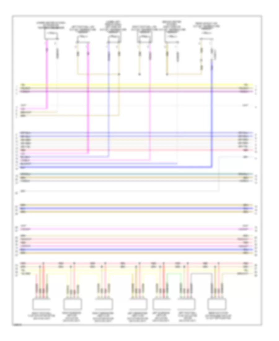
Automatic A/C Wiring Diagram, with Thermotronic (1 of 4) for Mercedes-Benz ML550 2012

List of elements for Automatic A/C Wiring Diagram, with Thermotronic (1 of 4) for Mercedes-Benz ML550 2012:
- (-)
- (under center console) w1/4
- 30g
- Air recirculation mode button
- Automatic air conditioning control & operating unit
- Battery compartment prefuse box (under right front seat)
- Booster blower electronic blower controller (on blower motor)
- C13a
- C19a
- Can b h
- Can b l
- Cbr bg
- Cockpit fuse box
- Computer data lines system
- Coolant circulation pump (in left front wheelwell)
- Defogger system
- Fresh air & air recirculation flap actuator motor (on hvac unit)
- Fuse 10a
- Fuse 150a
- Fuse 15a
- Fuse 25a
- Fuse 40a
- Gnd
- High side
- Hot at all times
- Info not available
- Interior prefuse box
- Kmv sk (+)
- Kmv sk (-)
- Komp pwr
- Komp rv(-)
- Lin
- Lin b8 (+)
- Lin b8 data
- Lin b8 gnd
- Lin b8 rf
- Lin data
- Nca
- Rear air conditioning electronic blower controller (if equipped)
- Rear blower motor
- Red
- S14
- S22
- Sig
- Sig li
- Sig re
- Temp ka sig
- Temp v sig
- Vdf
- Vent v
- W1/4 (under center console)
- W6 (left "d" pillar)
- W9 (left side of engine compt)
- Wake up
- X122/2-c2
- X122/3-c1
- X18-c1
- X25/2-c1
- X26/4-c1
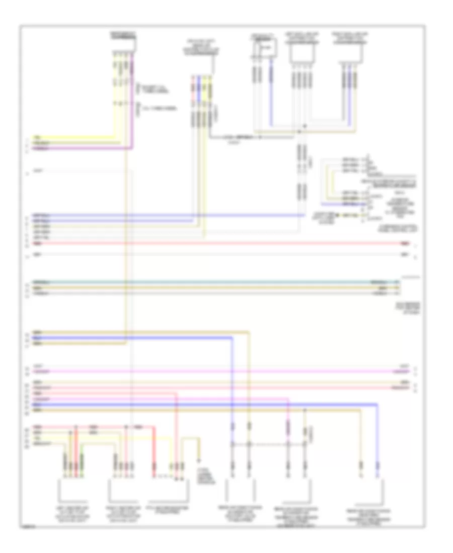
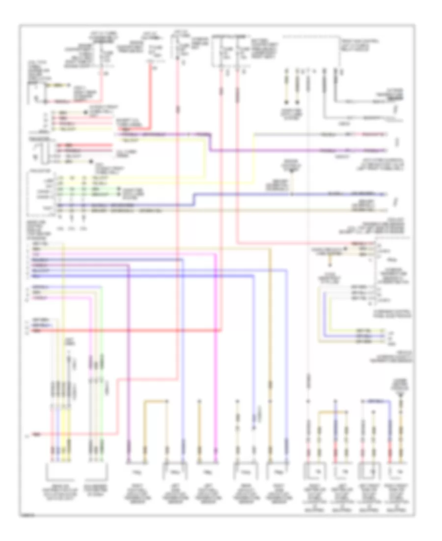
Automatic A/C Wiring Diagram, with Thermotronic (2 of 4) for Mercedes-Benz ML550 2012
List of elements for Automatic A/C Wiring Diagram, with Thermotronic (2 of 4) for Mercedes-Benz ML550 2012:
- (behind center of dash) right side air outlet temperature sensor
- (under center of dash) evaporator temperature sensor
- (under left side of dash) left side air outlet temperature sensor
- Left blending air flap actuator (on hvac unit)
- Left defroster vent flap actuator motor (on hvac unit)
- Left footwell air outlet temperature sensor
- Left footwell flap actuator motor (on hvac unit)
- Rear actuator motor blend air flap w/ cut off function
- Rear air duct air outlet temperature sensor
- Red
- Right blending air flap actuator (on hvac unit)
- Right defroster vent flap actuator motor (on hvac unit)
- Right footwell air outlet temperature sensor
- Right footwell flap actuator motor (on hvac unit)
- X122/2-c1
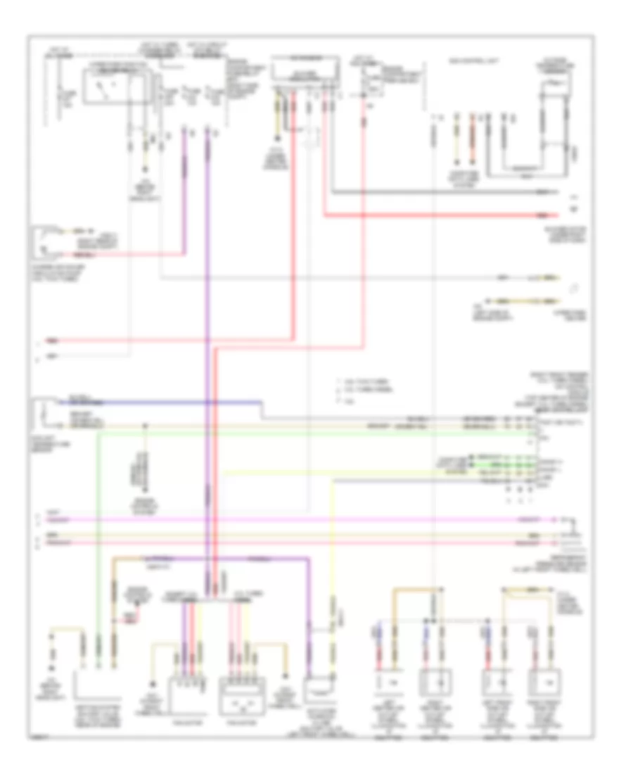
Automatic A/C Wiring Diagram, with Thermotronic (3 of 4) for Mercedes-Benz ML550 2012
List of elements for Automatic A/C Wiring Diagram, with Thermotronic (3 of 4) for Mercedes-Benz ML550 2012:
- (on hvac unit) rear air distribution flap actuator motor
- 3.0l turbo diesel
- Air quality sensor
- Computer data lines system
- Except 3.0l turbo diesel
- Gnd
- Interior temperature sensor w/ integrated fan
- Left b-pillar air distribution actuator motor
- Left center air outlet flap actuator motor (on hvac unit)
- Lin b13
- Nca
- Overhead control panel control unit
- Ptc heater booster (if equipped)
- Rear air conditioning evaporator shutoff valve (if equipped)
- Rear air conditioning evaporator temperature sensor (if equipped) (on rear hvac unit)
- Rear air conditioning head area temperature sensor (if equipped)
- Red
- Refrigerant compressor
- Right b-pillar air distribution actuator motor
- Right center air outlet flap actuator motor (on hvac unit)
- Sun sensor (top center of dash)
- Vehicle interior humidity & temperature sensor
- W15/9 (under center console)
- X122/2-c1
- X122/3-c2
- X18-c1
- X22/2-c2
- X26-c1
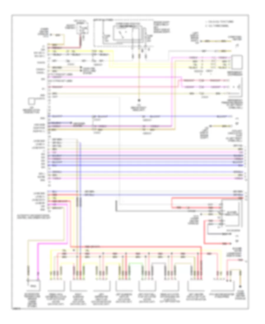
Automatic A/C Wiring Diagram, with Thermotronic (4 of 4) for Mercedes-Benz ML550 2012
List of elements for Automatic A/C Wiring Diagram, with Thermotronic (4 of 4) for Mercedes-Benz ML550 2012:
- (-)
- (or tmot1)
- (right front fender) (3.0l turbo diesel) cdi control module (top center of engine) (except 3.0l turbo diesel) me-sfi control unit
- 25/2-c1
- 3.0l turbo diesel
- 3.5l
- 4.6l twin turbo
- Aav
- Ac housing
- Activated charcoal filter shutoff valve (left front wheelwell)
- Blower motor (under right side of dash)
- Blower regulator
- Can-e1 h
- Can-e1 l
- Charge air cooler circulation pump (4.6l twin turbo)
- Computer data lines system
- Coolant temperature sensor
- Engine compartment fuse/relay box (right side of engine compt)
- Engine compartment prefuse box
- Engine controls system
- Except 3.0l turbo diesel
- Fan motor
- Fuse 10a
- Fuse 125a
- Fuse 15a
- Fuse 20a
- Hav
- Heating system shutoff valve (4.6l twin turbo) (rear of engine)
- Hot at all times
- Hot w/ circuit 87m relay energized
- Hot w/ turbo charger relay energized
- Left center air outlet symbol illumination (if equipped)
- Left front side air outlet symbol illumination (if equipped)
- Lues
- Mr1
- Nca
- Outside temperature sensor
- Pwm
- Red
- Refrigerant pressure sensor (in left front wheelwell)
- Right center air outlet symbol illumination (if equipped)
- Right front side air outlet symbol illumination (if equipped)
- Sam control unit
- Tmot
- Uhi
- W1/4 (under center console)
- W2 (behind right headlight)
- W2/1 (in right front wheelwell)
- W52/11 (right rear of engine compt)
- W9 (left side of engine compt)
- Wiper park heater
- Wiper park position heater relay
- X26/31-c1
- X26/32
Automatic A/C Wiring Diagram, without Thermotronic (1 of 2) for Mercedes-Benz ML550 2012
List of elements for Automatic A/C Wiring Diagram, without Thermotronic (1 of 2) for Mercedes-Benz ML550 2012:
- (-)
- (5 to 7 pins not used)
- (9 & 10 pins not used)
- (left side of engine compt) w9
- (under center console) w1/4
- 3.0l turbo diesel
- 3.5l & 4.6l twin turbo
- 30g
- A/c housing
- Air recirculation mode button
- Automatic air conditioning control and operating unit
- Blower motor (under right side of dash)
- Blower regulator
- C19a
- Can-b h
- Can-b l
- Cockpit fuse box
- Computer data lines system
- Coolant circulation pump (in left front wheelwell)
- Defogger system
- Engine compt fuse & relay box (right side of engine compt)
- Evaporator temperature sensor (under center of dash)
- Fresh air & air recirculation flap actuator motor (on hvac unit)
- Fuse 15a
- Fuse 20a
- Gnd
- High side
- Hot at all times
- Kmv sk (+)
- Kmv sk (-)
- Komp pwr
- Komp rv (-)
- Left blending air flap actuator (on hvac unit)
- Left center air outlet flap actuator motor
- Left defroster vent flap actuator motor (on hvac unit)
- Left footwell flap actuator motor (on hvac unit)
- Lin b8 (+)
- Lin b8 data
- Lin b8 gnd
- Lin b8 rf
- Lin data
- Mr1
- Nca
- Ptc heater booster (if equipped)
- Rear actuator motor blend air flap with cut off function
- Red
- Refrigerant compressor
- Refrigerant pressure sensor (in left front wheelwell)
- Right blending air flap actuator (on hvac unit)
- Sig
- Sig li
- Sig re
- Vdf
- W1/4 (under center console)
- W15/9 (under center console)
- W2 (behind right headlight)
- W9 (left side of engine compt)
- Wah7g
- Wiper park heater
- Wiper park position heater relay
- X18-c1
- X18-c2
- X22/2-c2
- X25/2-c1
- X26-c1
Automatic A/C Wiring Diagram, without Thermotronic (2 of 2) for Mercedes-Benz ML550 2012
List of elements for Automatic A/C Wiring Diagram, without Thermotronic (2 of 2) for Mercedes-Benz ML550 2012:
- (-)
- (4.6l twin turbo) charge air cooler circulation pump
- (in right front wheelwell) w2/1
- (not used)
- (under center console) w1/4
- 3.0l
- 3.0l turbo diesel
- 3.5l
- 4.6l
- Aav
- Activated charcoal filter shutoff valve (left front wheelwell)
- Battery compartment prefuse box (under right front seat)
- Can-e1 h
- Can-e1 l
- Computer data lines system
- Coolant temperature sensor (3.0l: top left side of engine) (except 3.0l: left rear of engine)
- Engine compartment fuse & relay box (right side of enigne compt)
- Engine compartment prefuse box
- Engine controls system
- Except 3.0l turbo diesel
- Fan motor
- Front sam control unit w/ fuse & relay module
- Fuse 10a
- Fuse 125a
- Fuse 150a
- Fuse 15a
- Fuse 40a
- Gnd
- Hot at all times
- Hot w/ turbo charger relay energized
- Interior prefuse box
- Interior temperature sensor w/ integrated fan
- Left center air outlet symbol illumination (if equipped)
- Left footwell air outlet temperature sensor
- Left front side air outlet symbol illumination (if equipped)
- Left side air outlet temperature sensor
- Lin
- Lin b13
- Lues
- Me-sfi (me) control module (top center of engine)
- Outside temperature sensor
- Overhead control panel electronics
- Pwm
- Rear air distribution flap actuator motor (on hvac unit)
- Rear air duct air outlet temperature sensor
- Red
- Right center air outlet symbol illumination (if equipped)
- Right footwell air outlet temperature sensor
- Right front side air outlet symbol illumination (if equipped)
- Right side air outlet temperature sensor
- S14
- Sun sensor (top center of dash)
- Tmot
- Uhi
- Vehicle interior humidity/ temperature sensor
- W18/5 (near right "a" pillar)
- W2/1 (in right front wheelwell)
- W52/11 (right rear of engine compt)
- X122/2-c1
- X18-c1
- X25/2-c1
- X26/32
- X26/4-c1