AIR CONDITIONING
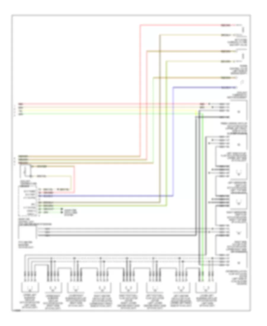
Automatic A/C Wiring Diagram (1 of 5) for Mercedes-Benz S550 2014

List of elements for Automatic A/C Wiring Diagram (1 of 5) for Mercedes-Benz S550 2014:
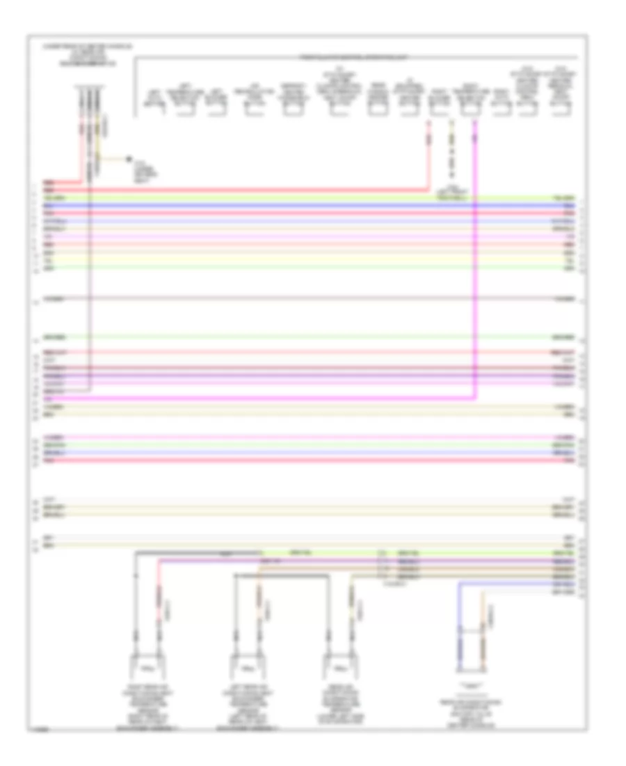
Automatic A/C Wiring Diagram (2 of 5) for Mercedes-Benz S550 2014
List of elements for Automatic A/C Wiring Diagram (2 of 5) for Mercedes-Benz S550 2014:
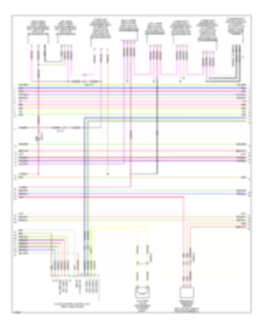
Automatic A/C Wiring Diagram (3 of 5) for Mercedes-Benz S550 2014
List of elements for Automatic A/C Wiring Diagram (3 of 5) for Mercedes-Benz S550 2014:
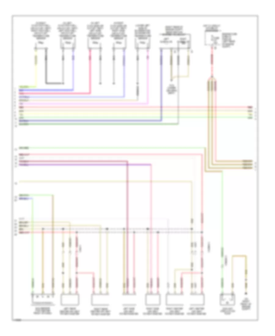
Automatic A/C Wiring Diagram (4 of 5) for Mercedes-Benz S550 2014
List of elements for Automatic A/C Wiring Diagram (4 of 5) for Mercedes-Benz S550 2014:
Automatic A/C Wiring Diagram (5 of 5) for Mercedes-Benz S550 2014
List of elements for Automatic A/C Wiring Diagram (5 of 5) for Mercedes-Benz S550 2014: