AIR CONDITIONING
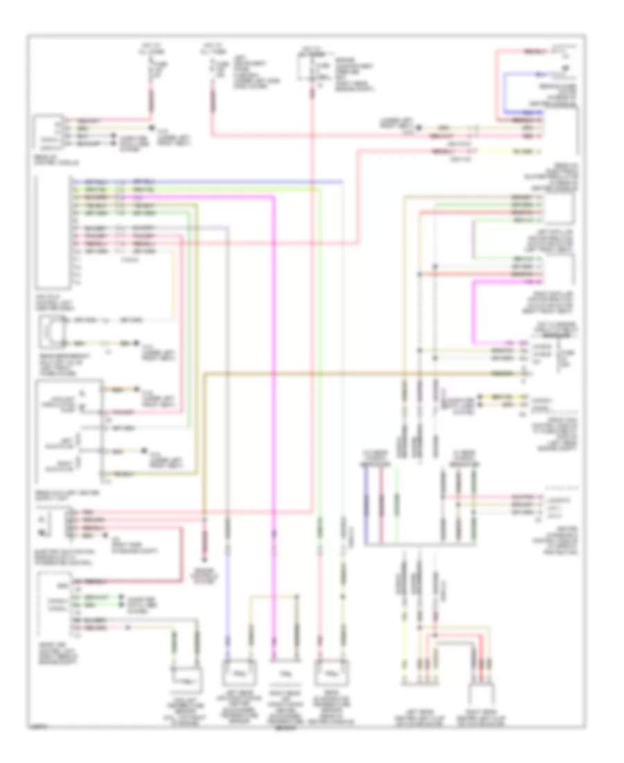
Automatic A/C Wiring Diagram (1 of 3) for Mercedes-Benz S550 4Matic 2010

List of elements for Automatic A/C Wiring Diagram (1 of 3) for Mercedes-Benz S550 4Matic 2010:
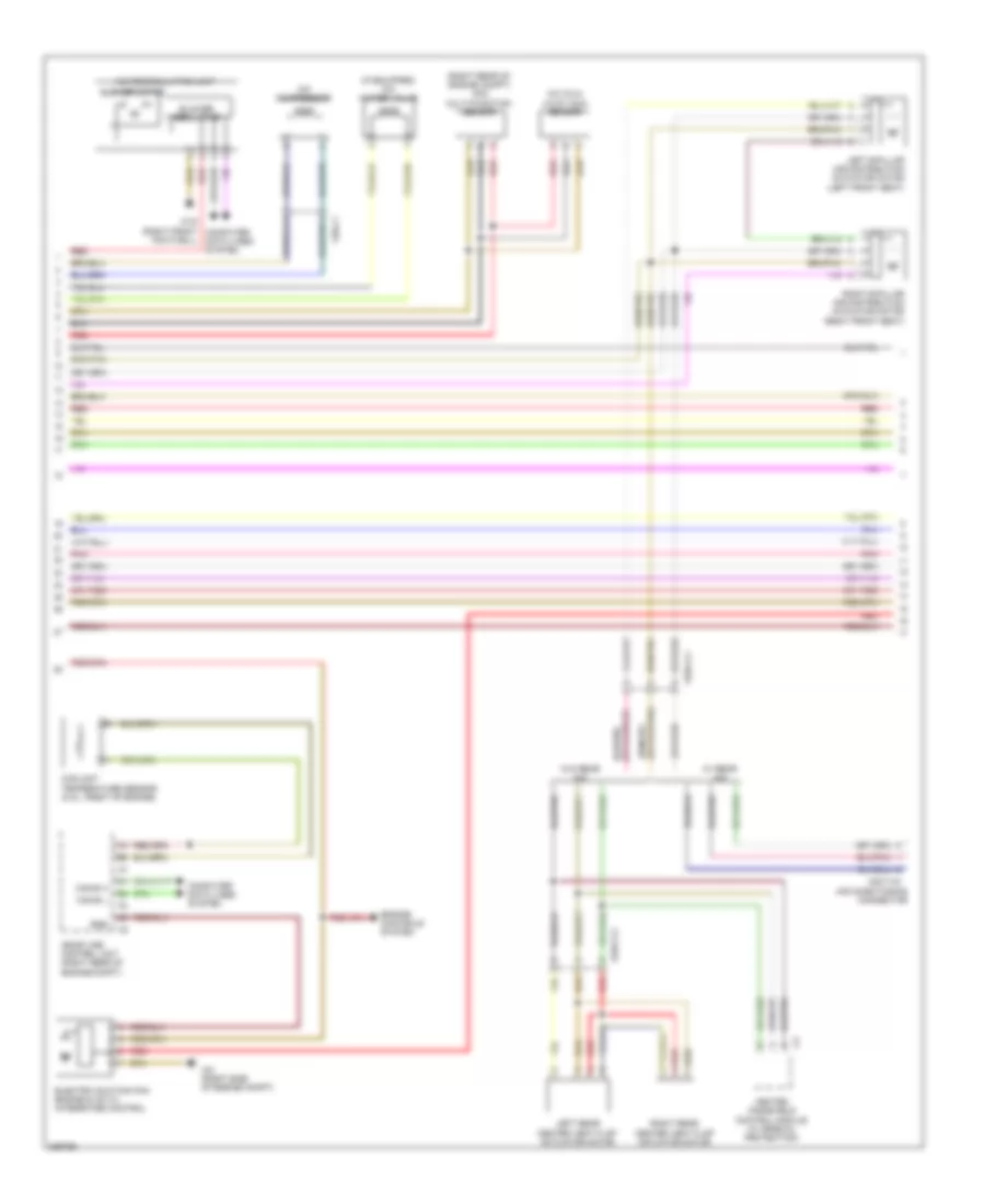
Automatic A/C Wiring Diagram (2 of 3) for Mercedes-Benz S550 4Matic 2010
List of elements for Automatic A/C Wiring Diagram (2 of 3) for Mercedes-Benz S550 4Matic 2010:
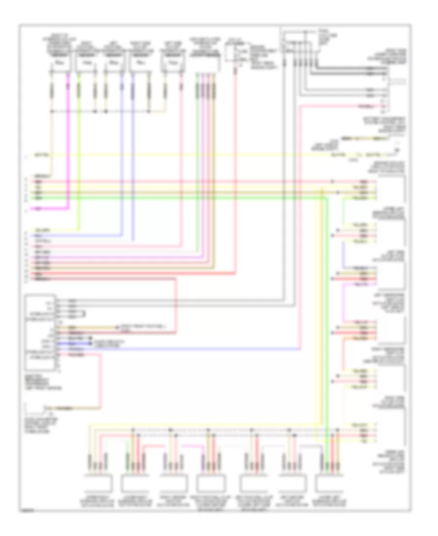
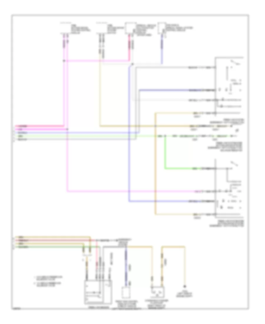
Automatic A/C Wiring Diagram (3 of 3) for Mercedes-Benz S550 4Matic 2010
List of elements for Automatic A/C Wiring Diagram (3 of 3) for Mercedes-Benz S550 4Matic 2010:
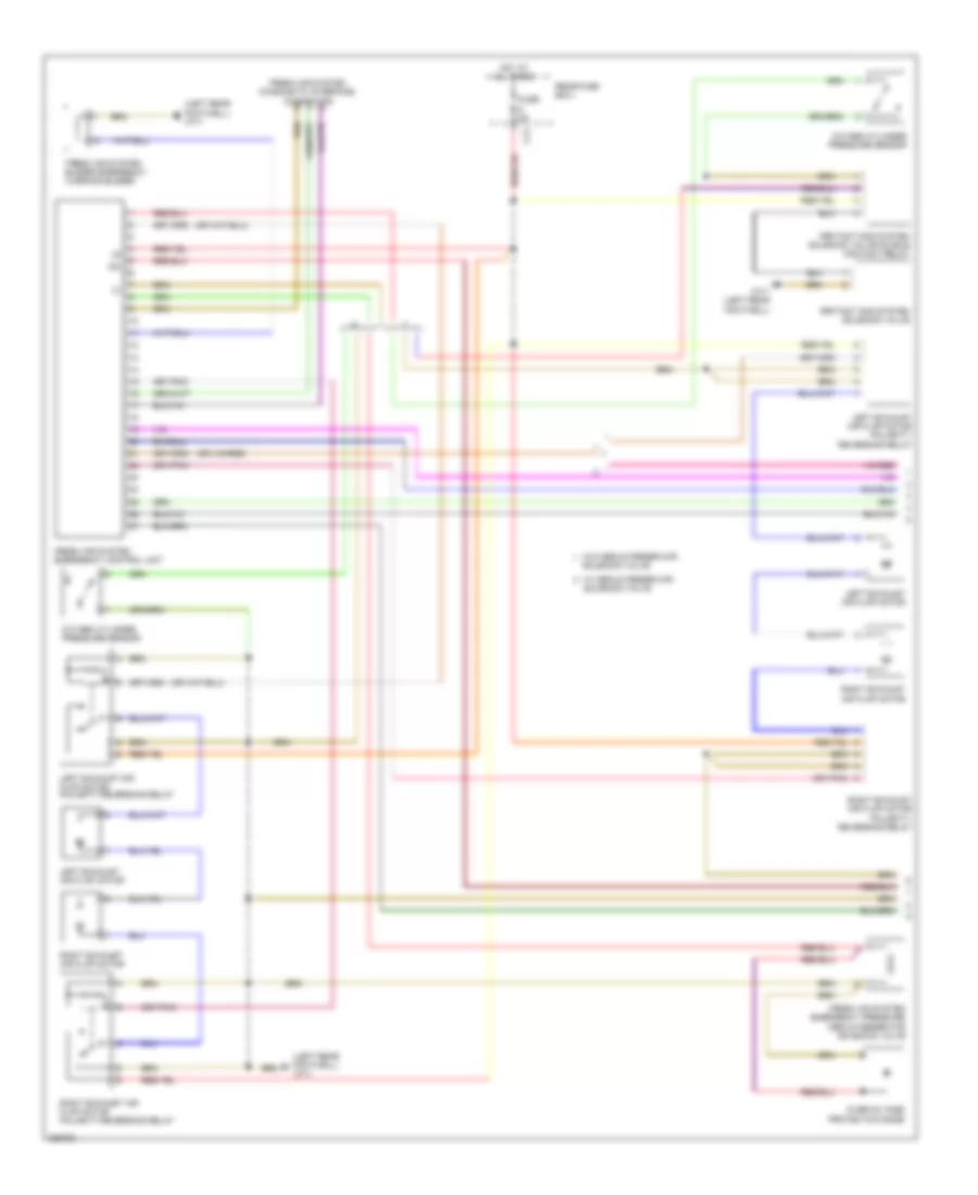
Fresh Air Emergency System Wiring Diagram (1 of 2) for Mercedes-Benz S550 4Matic 2010
List of elements for Fresh Air Emergency System Wiring Diagram (1 of 2) for Mercedes-Benz S550 4Matic 2010:
Fresh Air Emergency System Wiring Diagram (2 of 2) for Mercedes-Benz S550 4Matic 2010
List of elements for Fresh Air Emergency System Wiring Diagram (2 of 2) for Mercedes-Benz S550 4Matic 2010:
Rear A/C Wiring Diagram for Mercedes-Benz S550 4Matic 2010
List of elements for Rear A/C Wiring Diagram for Mercedes-Benz S550 4Matic 2010: