AIR CONDITIONING
Automatic A/C Wiring Diagram for Mercury Grand Marquis GS 2004

List of elements for Automatic A/C Wiring Diagram for Mercury Grand Marquis GS 2004:
- (at center rear of engine) g106
- (at front of right front fender apron) g102
- (at front of right front fender apron) g102
- (behind right kick panel) g201
- (in main wiring harness, on left rear side of engine compt) s286
- (left rear of engine compt)
- (left rear of engine compt) s156
- (near breakout to c1019) s109
- (near breakout to c1033) s123
- (near breakout to c1046) s113
- (near breakout to coil on plug 2) s157
- (near breakout to coil on plug 4)
- (near breakout to speed control actuator) s128
- (not used)
- A/c clutch field coil (at right front of engine)
- A/c clutch relay
- A/c evaporator discharge temperature sensor (on right side rear of engine compt)
- A/c pressure transducer sensor (on right side center of engine)
- Air bag sliding contact (at base of steering column)
- Amb temp sens input
- Ambient air temperature sensor (on front of upper radiator support)
- Audio/climate control system
- Autolamp/sunload sensor (on upper left side of dash)
- Battery
- Battery junction box (bjb) (in right front of engine compartment, behind battery)
- Blend door (heat)
- Blower motor high message center switch out blend door (cool)
- Blower motor relay
- Blower mtr output
- Blower speed ctrl
- C2145a
- C220b
- C228a
- C228b
- Central junction box (cjb) (below dash, left of steering column)
- Computer data lines system
- Control module)
- Eatc module
- Electronic automatic temperature control (eatc) module (behind center of dash)
- Engine controls system
- Engine coolant temperature (ect) sensor (except marauder: on top right front of engine, near fuel injector 1) (marauder: at front top left of engine)
- Engine cooling fan motor (front of engine compt)
- Fan down
- Fan up
- Front blower motor (at right rear of engine compt)
- Front blower motor speed controller (at rear of engine compt)
- Front fender apron) g102
- Front panel illum
- Fuse 15a
- Fuse 40a
- Fuse 50a
- G201 (behind right kick panel)
- Ground
- Hot at all times
- Hot in run
- Hot in run or acc
- Hot in run or start
- Ignition
- In car temp sens
- In-vehicle temperature sensor (behind top center of dash)
- Instrument cluster (electronic cluster)
- Instrument illum
- Interior lights system
- Lighting control module (behind center of dash)
- Low charge protection sw
- Low charge protection switch (at right side of of engine compt)
- Nca
- Pcm power relay
- Powertrain control module (pcm) (in engine compt on left side of firewall)
- Red
- Remote ctrl unit
- Rest
- S113 (in dash panel to headlamp junction harness, near breakout to c1046)
- S122 (in dash panel to headlamp junction harness, left rear of engine compartment)
- S126
- S130 (left rear of engine compt)
- S133 (left rear of engine compt)
- S136
- S141 (in dash panel to headlamp junction harness, near breakout to c1026)
- S142 (in dash panel to headlamp junction harness, in breakout to engine cooling fan motor)
- S227 (in main wiring harness, near breakout to lighting control module)
- S276 (in main wiring harness, near breakout to autolamp sensor)
- S285 (in main wiring harness, near breakout to adjustable pedal switch)
- Scp bus (+)
- Scp bus (-)
- Sensor rtn
- Sunload sens input
- Temp door variable resistor
- Temp down
- Temp up
- Temperature blend door actuator (behind right side of dash, on top of a/c plenum)
- To autolamp sensor)
- Variable resistor
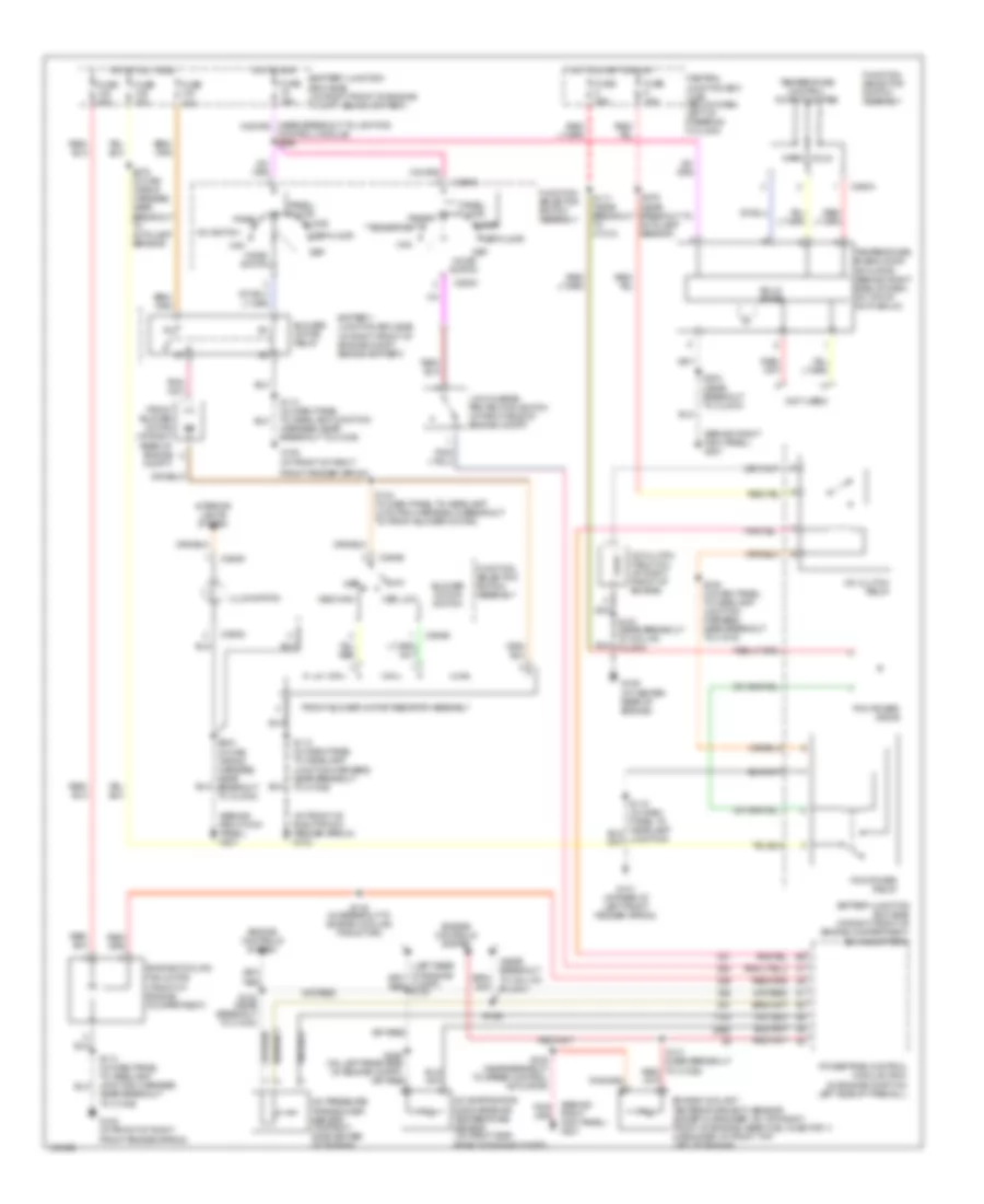
Manual A/C Wiring Diagram for Mercury Grand Marquis GS 2004
List of elements for Manual A/C Wiring Diagram for Mercury Grand Marquis GS 2004:
- (at front of right
- (at front of right front fender apron) g102
- (behind right kick panel) g201
- (front of engine compartment)
- (in engine compt on left side of firewall)
- (near breakout to coil on plug 4)
- (not used)
- A/c clutch field coil (at right front of engine)
- A/c clutch relay
- A/c evaporator discharge air temperature sensor (on right side rear of engine compt)
- A/c pressure transducer sensor (on right side center of engine)
- A/c switch
- Battery junction box (bjb) (in right front of engine compartment, behind battery)
- Battery junction box (bjb) (in right front of engine compt, behind battery)
- Blower motor relay
- Blower motor switch
- C294a
- C294b
- C294c
- C294d
- Central junction box (cjb) (below dash, left of steering column)
- Cold
- Compt)
- Control module) s266
- Def
- Def/floor
- Engine controls system
- Engine coolant temperature (ect) sensor (except marauder: on top right front of engine, near fuel injector 1) (marauder: at front top left of engine)
- Engine cooling fan motor
- Floor
- Front blower motor (at right rear of engine
- Front blower motor resistor assembly
- Front fender apron)
- Function selector switch assembly
- Fuse 15a
- Fuse 25a
- Fuse 30a
- Fuse 40a
- Fuse 50a
- G101 (at rear of left front fender apron)
- G102
- G102 (at front of right
- G106 (at center rear of engine)
- High
- Hot at all times
- Hot in run
- Hot in start or run
- Illumination
- Interior lights system
- Low
- Low charge protection switch (at right side of engine compt)
- Max
- Med high
- Med low
- Mode switch
- Off
- Panel
- Panel/ floor
- Pcm power diode
- Pcm power relay
- Powertrain control module (pcm)
- S109 (in dash panel to headlamp junction harness, near breakout to c1019)
- S113 (in dash panel to headlamp junction harness, near breakout
- S113 (in dash panel to headlamp junction harness, near breakout to c1046)
- S117 (near breakout to c1010)
- S123 (near breakout to c1033)
- S126
- S128 (near breakout to speed control actuator)
- S142 (in breakout to engine cooling fan motor)
- S144 (in dash panel to headlamp junction harness, in breakout to front blower motor)
- S157 (near breakout to coil on plug 2)
- S204 (in main wiring harness, near breakout to clock)
- S204 (near breakout to clock)
- S276 (in main wiring harness, near breakout to autolamp sensor)
- S276 (near breakout to autolamp sensor)
- Solid state
- Temperature blend door actuator (behind right side of dash, on top of a/c plenum)
- Temperature control potentiometer
- To c1046)
- Warm