AIR CONDITIONING
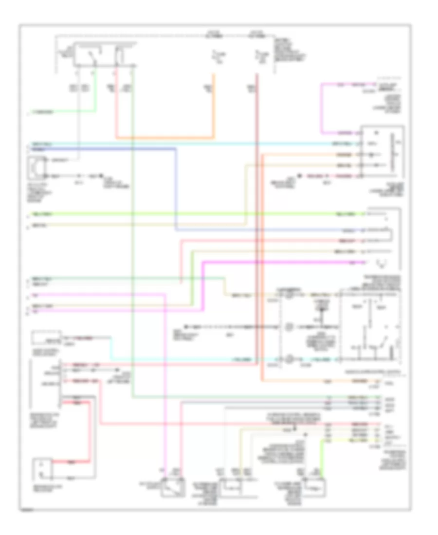
Automatic A/C Wiring Diagram (1 of 2) for Mercury Grand Marquis LS 2009

List of elements for Automatic A/C Wiring Diagram (1 of 2) for Mercury Grand Marquis LS 2009:
- A/c output
- Amb temp sens input
- Ambient air temperature sensor (front of upper radiator support)
- Battery
- Battery junction box (bjb) (right front of engine compt, behind battery)
- Blend door cool
- Blend door heat
- Blower
- Blower motor high
- Blower motor relay
- C228a
- C228b
- Central junction box (cjb) (below dash, left of steering column)
- Computer data lines system
- Eatc hvac module
- Front blower motor (right rear of engine compt)
- Front blower motor speed controller (at rear of engine compt)
- Fuse 10a
- Fuse 15a
- Fuse 40a
- G109 (front of right fender)
- G203 (behind right kick panel)
- Ground
- Hot at all times
- Hot in start
- In car temp sens
- In-vehicle temperature sensor (behind center of dash)
- Interior lights system
- Pot feed
- Pot feedback
- Pot rtn
- Pwm illum
- Run
- S121
- S207
- Scp bus (+)
- Scp bus (-)
- Sens rtn
- Steering wheel ctrl
- Sunload sens input
- Variable volt dim
- Vbc hbr
- Vbc input
- Vbc output
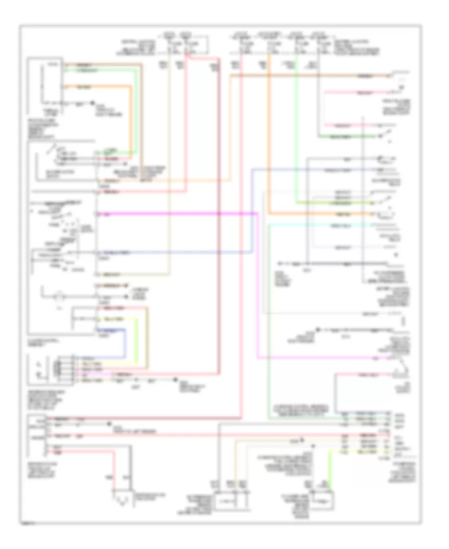
Automatic A/C Wiring Diagram (2 of 2) for Mercury Grand Marquis LS 2009
List of elements for Automatic A/C Wiring Diagram (2 of 2) for Mercury Grand Marquis LS 2009:
- (in engine control sensor & fuel charge wiring harness, near breakout to cop 4)
- A/c clutch field coil (lower right front of engine)
- A/c clutch relay
- A/c cycling switch
- A/c pressure transducer sensor (on right side center of engine)
- Accr
- Accs
- Acpt
- Audio control module (acm)
- Audio/climate control switch
- Autolamp sensor
- Autolamp sensor (under upper left side of dash)
- Battery junction box (bjb) (right front of engine compt, behind battery)
- C175b
- C175e
- C175t
- C2145a
- C218a
- C218b
- C290a
- Cht
- Clockspring
- Control solid state
- Cylinder-head temperature sensor (top left front of engine)
- Engine cooling fan module (left front of engine compt)
- Engine cooling fan motor
- Fc v
- Fuse 15a
- Fuse 50a
- G102 (front of left fender)
- G109 (front of right fender)
- G201 (behind right kick panel)
- G203 (behind right kick panel)
- Ground
- Hot at all times
- Interior lights system
- Lighting control module (under center of dash)
- Next
- Patil
- Powertrain control module (pcm) (left rear of engine compt)
- Pwr
- Red
- Remote
- S114
- S123 (in engine control sensor & fuel charge wiring harness, near breakout to powertrain control module (pcm))
- S126
- S201
- S210
- S294 (in breakout to steering wheel/ speed control switch)
- Sig rtn 1
- Temp+
- Temp-
- Temperature blend door actuator (behind right side of dash, on top of a/c plenum)
- Var spd in
- Vol+
- Vol-
- Vref
Manual A/C Wiring Diagram for Mercury Grand Marquis LS 2009
List of elements for Manual A/C Wiring Diagram for Mercury Grand Marquis LS 2009:
- (in engine control sensor & fuel charge wiring harness, near breakout to cop 4)
- (left rear of engine compt)
- (right rear of engine compt) s122
- A/c clutch field coil (lower right front of engine)
- A/c clutch relay
- A/c compressor clutch diode (early production)
- A/c cycling switch
- A/c max a/c
- A/c pressure transducer sensor (on right side center of engine)
- Accr
- Accs
- Acpt
- Battery junction box (bjb) (right front of engine compt, behind battery)
- Blower motor relay
- Blower motor switch
- C175b
- C175e
- C294a
- C294b
- C294c
- C294d
- Central junction box (cjb) (below dash, left of steering column)
- Cht
- Climate control assembly
- Control circuit
- Cylinder-head temperature sensor (top left front of engine)
- Def/floor
- Defrost
- Defrost def/floor
- Engine cooling fan module (left front of engine compt)
- Engine cooling fan motor
- Fc v
- Floor
- Front blower motor (right rear of engine compt)
- Front blower motor resistor assembly (rear of engine compt)
- Fuse 10a
- Fuse 15a
- Fuse 40a
- Fuse 50a
- G102 (front of left fender)
- G109 (front of right fender)
- G203 (behind right kick panel)
- G204 (behind right kick panel)
- Ground
- High
- Hot at all times
- Hot in run
- Hot in start or run
- Ill
- Interior lights system
- Low
- Max a/c a/c
- Med high
- Med low
- Mode switch
- Off
- Pan/floor
- Panel
- Powertrain control module (pcm)
- Pwr
- Red
- S114
- S121
- S123 (in engine control sensor & fuel charge wiring harness, near breakout to powertrain control module (pcm))
- S126
- S207
- Sig rtn 1
- Temperature blend door actuator (behind right side of dash, on top of a/c plenum)
- Thermal limiter
- Var spd
- Vref