AIR CONDITIONING
A/C Wiring Diagram, Auto A/C for Mercury Sable GS 1996

List of elements for A/C Wiring Diagram, Auto A/C for Mercury Sable GS 1996:
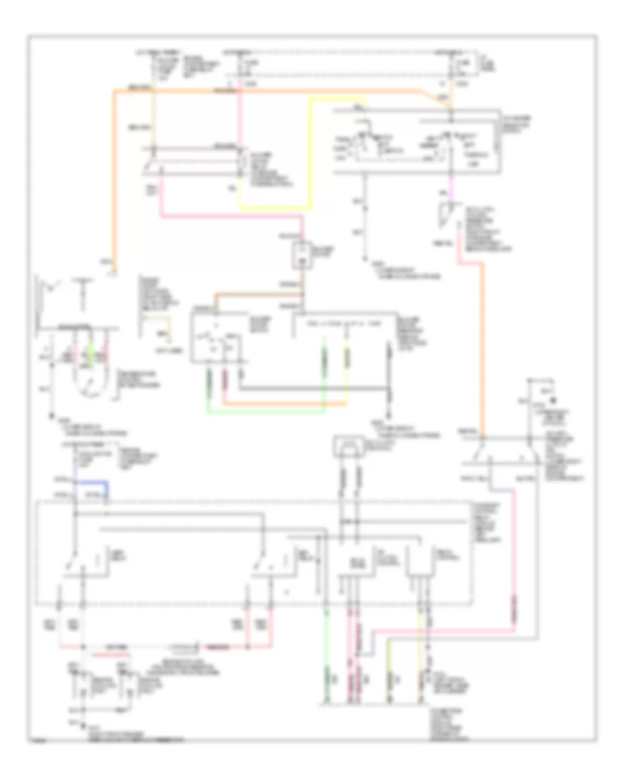
A/C Wiring Diagram, Manual A/C for Mercury Sable GS 1996
List of elements for A/C Wiring Diagram, Manual A/C for Mercury Sable GS 1996: